Description
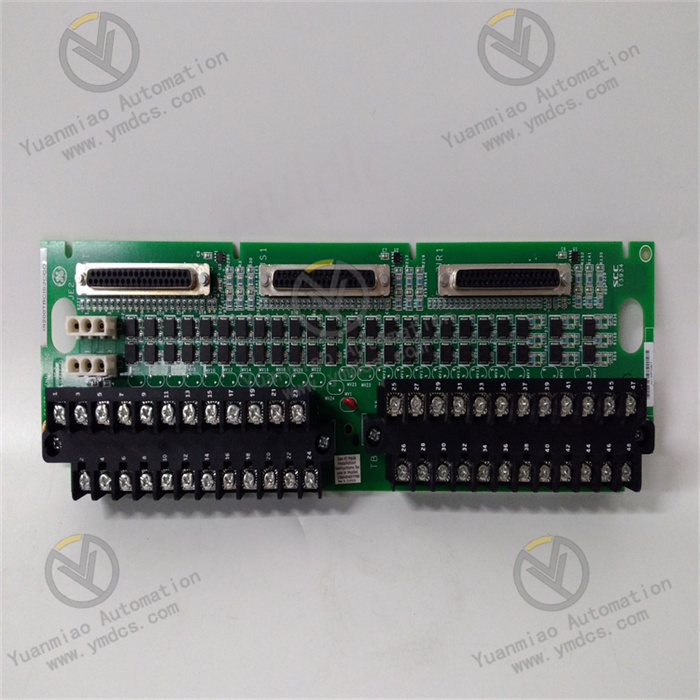
GE IS200TBTCH1C
The GE IS200TBTCH1C is a high-performance thermocouple input module, serving as a key signal acquisition component of the Mark VI series control system. Its core positioning is a precise acquisition and processing unit for thermocouple (TC) signals in large-scale industrial equipment (such as steam turbines, gas turbines, boilers, chemical reactors, etc.). Through a dedicated thermocouple signal conditioning circuit and digital conversion technology, this module converts on-site thermocouple signals within different temperature ranges into stable digital signals, which are uploaded to the control system to realize real-time temperature monitoring, abnormal early warning, fault diagnosis, and interlock protection. It provides highly reliable data support for the safe operation of equipment, optimization of process parameters, and operation and maintenance management.
Relying on GE's mature technical accumulation in the field of industrial control, the IS200TBTCH1C module has core advantages such as multi-channel acquisition, high anti-interference capability, and flexible configuration. It is widely used in industries with strict requirements for temperature monitoring accuracy and reliability, including power generation, petrochemicals, iron and steel metallurgy, and new energy. It is perfectly compatible with the GE Mark VI steam turbine control system and also supports connection with mainstream DCS systems (such as Siemens PCS 7, Emerson DeltaV) and SIS (Safety Instrumented System) through standard protocols. The module adopts an enhanced electrical isolation design and a structure resistant to harsh environments, which can effectively withstand complex working conditions in industrial sites such as electromagnetic interference, vibration impact, and temperature-humidity fluctuations, ensuring the stability and accuracy of temperature data acquisition. In addition, the module supports online debugging and intelligent fault diagnosis functions, which significantly reduce operation and maintenance costs, making it a core adaptive component in industrial-grade temperature monitoring systems.
The module is equipped with 16 independent differential input channels, and each channel can be independently configured as 8 mainstream thermocouple types (including J/K/T/E/R/S/B/N) through configuration software. It can adapt to different temperature monitoring scenarios without hardware replacement. For example, in the steam turbine system of a thermal power plant: Type S thermocouples (withstanding 1600℃) are used for high-temperature components (such as turbine blades and main steam pipes); Type K thermocouples (with a wide range of -200℃~1372℃) are used for medium-temperature components (such as bearing housings and oil systems); Type T thermocouples (with high precision of -200℃~400℃) are used for low-temperature cooling systems. In the monitoring of chemical reactors: Type B thermocouples are used for high-temperature reaction zones inside the reactor, and Type E thermocouples are used for jacket heating zones. This realizes precise acquisition of multiple parts and multiple temperature ranges, greatly improving the adaptability and flexibility of the system. The 16-channel design can reduce the number of modules and lower system integration costs.
It adopts a 16-bit high-precision ADC chip and a dedicated thermocouple signal conditioning circuit, with a full-range measurement accuracy of ±0.1% FS and a minimum resolution of 0.01℃. It can accurately capture small temperature fluctuations of ±0.1℃ in steam turbine bearing pads, providing precise data support for early fault prediction such as bearing wear and seal failure. To address the cold-junction temperature drift issue in thermocouple measurement, the module is equipped with a built-in high-precision cold-junction compensation circuit with a compensation accuracy of ±0.2℃, which automatically offsets the impact of ambient temperature changes on measurement results. When the module is installed in a high-temperature control cabinet or a low-temperature environment (exceeding the range of 0℃~60℃), an external Pt100 sensor can be connected to achieve extended compensation, further improving measurement accuracy. In addition, a built-in thermocouple linearization correction algorithm eliminates system errors caused by the nonlinear characteristics of the sensor, ensuring true and reliable data.
It adopts a single-channel independent isolation design, with an isolation voltage of 1500V AC between channels and 2000V AC between channels and the power supply/ground. This can effectively avoid signal crosstalk between different channels and voltage surges generated by high-voltage equipment in industrial sites (such as excitation systems and high-voltage frequency converters). The core circuit adopts photoelectric isolation, differential signal transmission, and full-shielding wiring technology, combined with a dual mechanism of hardware RC filtering and programmable digital filtering. It can effectively suppress common interferences such as power frequency interference, electromagnetic radiation, and motor start-stop noise, and can still stably acquire data in harsh environments with concentrated frequency converters and high vibration in steel plants. The module housing is made of flame-retardant insulating materials and has passed the IEC 61000-4 series anti-interference tests, ensuring long-term stable operation under complex working conditions.
A built-in all-round intelligent fault diagnosis system can real-time monitor the power supply status, ADC conversion status, thermocouple connection status (open circuit, short circuit, reversed polarity), cold-junction compensation circuit status, and channel signal conditioning circuit faults, with a fault detection response time ≤10ms. When an abnormality is detected, it immediately uploads the fault code, fault channel, and specific type (such as "Reversed polarity of Type R thermocouple in Channel 7" and "Abnormal cold-junction compensation in Channel 12") to the controller and upper monitoring platform via the bus. At the same time, the red fault indicator light of the corresponding channel on the module surface lights up, allowing operation and maintenance personnel to quickly locate the fault point and shorten the traditional hour-level troubleshooting to minute-level. It supports multi-level alarm configuration including upper limit, lower limit, temperature rise rate, and deviation. Alarm thresholds can be flexibly set, and alarm signals can directly trigger sound and light alarms or equipment interlock protection (such as shutdown and starting the cooling system) to prevent fault expansion.
It supports full-parameter graphical configuration through GE Mark VI dedicated configuration software (such as Turbine Control Studio), enabling intuitive completion of operations such as thermocouple type selection for channels, filter time adjustment, cold-junction compensation mode setting, and alarm threshold configuration. No underlying programming is required, allowing beginners to get started quickly. Equipped with an RS485 debugging interface and supporting the Modbus-RTU protocol, operation and maintenance personnel can read real-time channel data on-site, modify parameters, and export fault records through a handheld terminal or laptop without disconnecting the system power supply, realizing live debugging and maintenance. The module surface is equipped with status indicator lights for power, operation, and fault, which can intuitively display the overall operating status, facilitating rapid on-site inspection and reducing the difficulty of operation and maintenance.
It is perfectly compatible with the GE Mark VI steam turbine control system and communicates with the controller through a 1Mbps high-speed backplane bus, with a data transmission delay ≤12μs. This ensures real-time upload of temperature data and meets the timeliness requirements of closed-loop regulation of the control system. It supports connection with mainstream DCS systems such as Siemens PCS 7 and Emerson DeltaV, as well as SIS systems through standard protocols, realizing centralized monitoring and cross-system sharing of temperature data. It supports 1+1 hot redundancy configuration; master and backup modules synchronize data and status in real time through a dedicated synchronization line. When the master module fails, the backup module automatically switches to operation within 60ms, with no data loss during the switching process. This ensures the continuity of temperature monitoring and avoids monitoring interruptions or equipment safety risks caused by a single module failure. The redundancy design enables the module to be used in scenarios with high safety requirements such as nuclear power and chemical industry.
![]()


