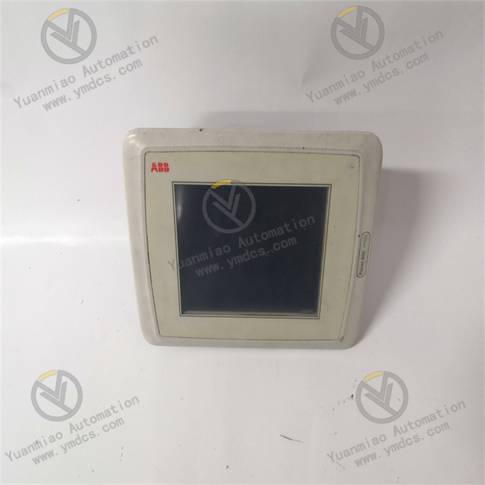
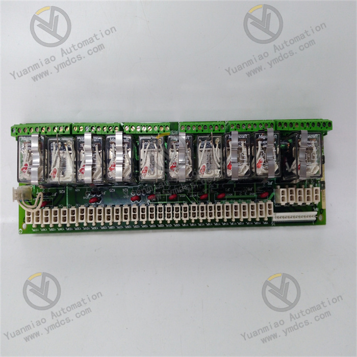
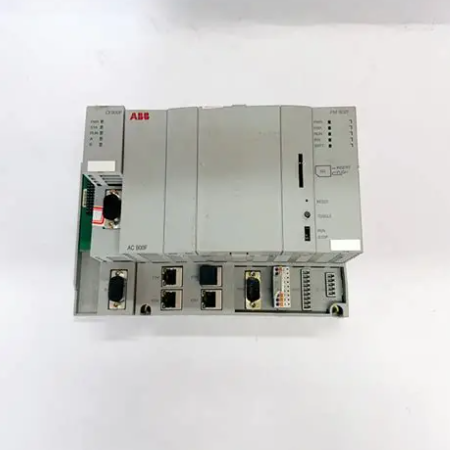
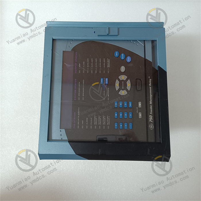
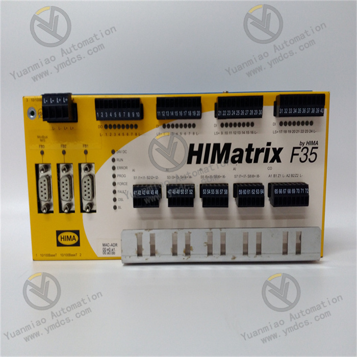
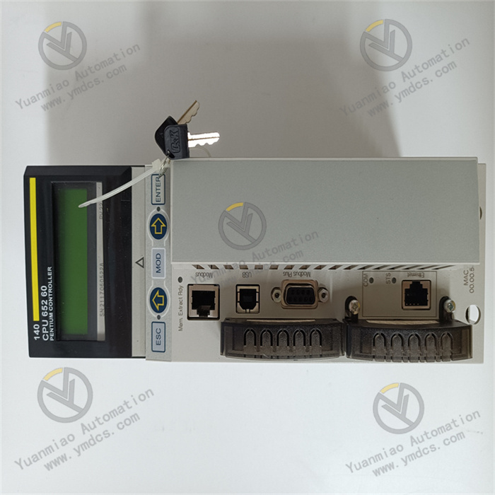
Description
Functional Features Measurement Function: As an analog measurement card, it is mainly used for accurately measuring and collecting analog signals in industrial fields, such as voltage, current, temperature, pressure and other signals. High Reliability: Complying with the high reliability standards of ABB's industrial products, it can work stably in harsh industrial environments, adapt to environmental conditions such as a wide temperature range, high humidity, and strong electromagnetic interference, and ensure the accuracy and stability of the measurement data. Communication Capability: It supports a variety of industrial communication protocols, enabling convenient communication and data interaction with other devices. It can be integrated with PLCs, DCS systems or other controllers, and transmit the measurement data to the upper computer or control system for further processing and analysis.

Application Scenarios Process Control Field: In continuous production processes such as the chemical, petroleum, natural gas, and power industries, it is used to monitor various process parameters, such as analog signals of flow rate, pressure, temperature, etc. in pipelines, providing accurate measurement data for the control system to achieve precise control and optimization of the production process. Automated Production Lines in the Manufacturing Industry: It can be used to monitor the operating status parameters of equipment on the production line, such as the current and temperature of motors, the pressure and displacement of mechanical components, etc. Through real-time measurement and analysis of these analog signals, it can achieve fault diagnosis, preventive maintenance of equipment, and quality control of the production process. Energy Management System: In scenarios such as power systems and energy distribution networks, it is used to measure electrical parameters such as voltage, current, and power, helping to achieve the monitoring, metering, and management of energy, and optimizing the efficiency of energy distribution and use. Installation Steps 1. Preparation before Installation Check the Integrity of the Equipment: Check whether the appearance of the module is damaged or deformed, and whether there is any foreign matter blocking each interface. At the same time, confirm whether the accessories (such as the instruction manual, cables, etc.) are complete. Prepare Tools: Prepare the tools required for installation, such as screwdrivers, wrenches, etc. Evaluate the Installation Environment: Ensure that the temperature, humidity, vibration and other conditions of the installation location meet the requirements of the module, and it is far away from strong electromagnetic interference sources and corrosive substances. Cut off the Power Supply: To ensure safety, the relevant power supply needs to be cut off before installation.

2. Installation Process Install on the Rack or Backplane If it is installed on the rack of a standard industrial control cabinet, carefully insert the module into the corresponding slot according to the slot position of the rack, and ensure that the module is closely connected to the slot. If it is installed on the backplane, install the module accurately in the designated position according to the installation instructions of the backplane, and connect the ribbon cables or interfaces well. Use fixing devices such as screws or buckles to secure the module in the installation position. Connect the Cables Power Cable: According to the power requirements of the module, connect the appropriate power cable, and pay attention to the power polarity and voltage range. Signal Cable: Connect the signal cables of devices such as sensors to the corresponding input ports of the module. When connecting, pay attention to the interface type and pin definition, ensure the connection is correct, and tighten the connectors to prevent loosening. Communication Cable: If the module supports the communication function, use the appropriate communication cable to connect it to the communication network, such as Ethernet, Profibus, etc. Grounding Connection: Connect the grounding terminal of the module to a reliable grounding wire, and ensure that the grounding resistance meets the requirements of the equipment. Generally, the grounding resistance should be less than the specified value (such as 4 ohms or 10 ohms).
3. Inspection after Installation Check the Connections: Recheck whether the connection between the module and the rack or backplane is firm, whether the cable connections are correct and not loose, and whether the grounding is good. Check the Power Supply: After confirming that the power connection is correct, turn on the power supply and check whether the power indicator light of the module is normally on to determine whether the module is powered on normally. Configuration Steps 1. Preparation before Configuration Obtain the Configuration Software: Download the configuration software suitable for this module from the official ABB website and install it on the computer. Establish a Communication Connection: Use the communication cable to connect the computer to the module and ensure normal communication. You can conduct a preliminary test by using commands such as the ping command.
2. Configuration Process
Launch the Configuration Software: Open the downloaded and installed configuration software.
Search for the Module: Use the search function in the software to find the connected module. The software will automatically identify the model and relevant information of the module.
Set Basic Parameters
Communication Parameters: According to the actual communication network and requirements, set the communication parameters of the module, such as baud rate, IP address, subnet mask, etc.
Measurement Parameters: For the measurement function of the module, set parameters such as the measurement range, accuracy, sampling frequency, etc. For example, if measuring voltage, it is necessary to set whether the measurement range of the voltage is 0 - 10V or other ranges.
Configure Input and Output
Input Configuration: According to the type of connected sensors and the characteristics of the signals, configure the input channels of the module, such as setting the type of input signals (voltage, current, etc.) and the range.
Output Configuration: If the module has an output function, set the type, range and trigger conditions of the output signals, etc.
Save the Configuration: After completing all the configurations, save the configuration parameters in the software and download them to the module.
3. Testing after Configuration
Function Test: Apply a known signal to the input port of the module, check whether the module can correctly collect and process the data, and check whether the measurement results are accurate through the software.
Communication Test: Interact with the module through the software to test whether the communication is normal and whether data upload and download can be achieved.

① 24 hours email response (12 hours);
② For shipment outside Asia, please contact the seller.
ABB Related Products
| 07KT94 GJR5252100R3261 | PFSK101 YM322001-ED |
| 07KP94 GJR5251700R0101 | PFSK102 YM322001-EG |
| 07KP95 GJR5252000R0101 | PFSK104 YM322001-EB |
| 07KP96 GATS110112R0001 | PFSK112 YM322001-ES |
| 07KR31 FPR3600227R1202 | PFSK107 YM322001-EE |
| 07KR51 1SBP260010R1001 | PFSK109 YM322001-EK |
| 07KT92 GJR5250500R0262 | PFSK113 YM322001-ET |
【 Disclaimer 】
We sell new products and discontinued products, independent channels to buy such special products. Guizhou Yuanmiao Automation Equipment Co., Ltd. is not an authorized distributor, dealer or representative of the products featured on this website. All product names/product images, trademarks, brands and microlabels used on this Website are the property of their respective owners. Descriptions, depictions or sales of products with such names/images, trademarks, brands and logos are for identification purposes only and do not imply any association or authorization with any rights holder.