Description
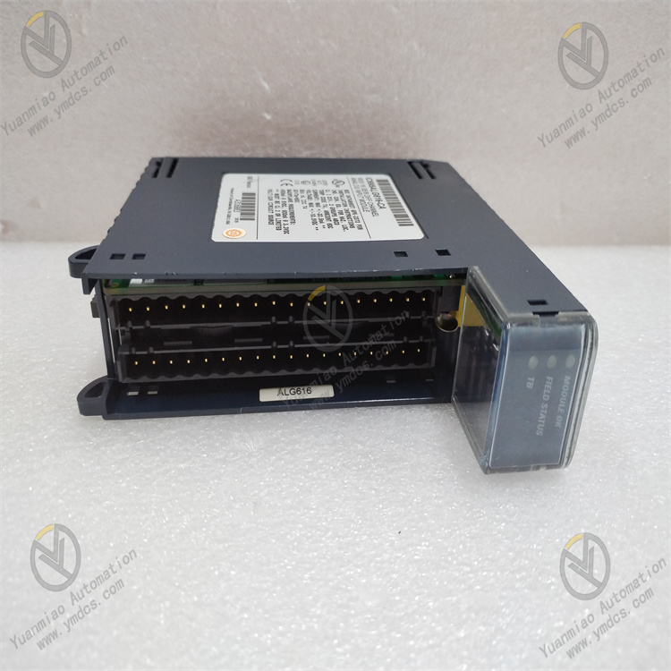
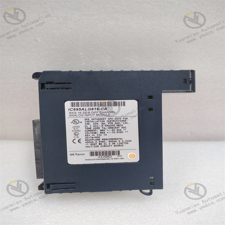
GE IC695ALG616-EA
I. Technical Parameters
1. Acquisition and Signal Parameters
- Adopts a 24-bit high-precision ADC converter, supporting two channel configuration modes: 16-channel single-ended or 8-channel differential, which can be flexibly switched according to the type of on-site sensors.
- Current acquisition range covers 0-20mA, 4-20mA, ±20mA; voltage acquisition range includes ±10V, 0-10V, ±5V, 0-5V, 1-5V and other specifications, compatible with signals from most industrial analog sensors.
- Data output format supports IEEE 32-bit floating-point numbers or 16-bit integers in 32-bit fields, configurable according to the requirements of the control system.
- Equipped with multi-level filtering options (8Hz, 12Hz, 16Hz, 40Hz, 200Hz, 500Hz). In normal mode, the noise suppression capability reaches 85dB@50/60Hz (at 8Hz filtering), and the common-mode rejection ratio (CMRR) is 120dB@50/60Hz (at 8Hz filtering), effectively ensuring acquisition accuracy under complex working conditions.
2. Hardware and Structural Parameters
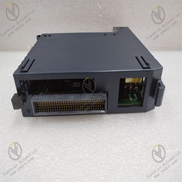
- Features a single-slot design, compatible with RX3i universal backplane installation. Module dimensions: 34mm×145mm×140mm, weight approximately 500g, with a compact structure and easy installation.
- Equipped with a detachable terminal block and a fully openable hinged door; the wiring diagram is printed directly on the back of the label for convenient on-site wiring and verification.
- Front panel is equipped with channel status LED indicators, providing intuitive feedback on the signal acquisition status and fault information of each channel.
- The terminal block has plug-in detection functionality, capable of real-time identifying the insertion or removal status of wiring terminals, facilitating operation and maintenance.
3. Power Supply and Power Consumption Parameters
- Backplane power supply requirements: 5.0V (±5%/±2.5%) with a maximum of 350mA, 3.3V (±5%/±3%) with a maximum of 200mA. Maximum module power consumption is 4.25W, no additional independent power supply required, simplifying system wiring.
- Equipped with overvoltage and overcurrent protection functions, capable of withstanding continuous ±60V DC overvoltage and ±28mA DC overcurrent, effectively resisting voltage and current shocks caused by on-site wiring errors or sensor abnormalities.
4. Environmental and Reliability Parameters
- Complies with industrial-grade wide-temperature operation standards: operating temperature range -25℃~+60℃, storage temperature range -40℃~+85℃, suitable for outdoor cabinets in cold regions and high-temperature workshop environments.
- Relative humidity adaptation range: 5%~95% (non-condensing), meeting the requirements of high-humidity environments such as coastal areas and humid mines.
- Excellent protection level and mechanical stability, supporting Class I, Division 2 hazardous area installation. Certified by multiple international standards including CE, ATEX C1D2, UL, ABS, DNV, and can be deployed in flammable and explosive scenarios such as petrochemical storage areas and gas processing stations.
5. Diagnostic and Calibration Parameters
- Equipped with full-process automatic calibration function, capable of automatic precision calibration during startup and operation, ensuring long-term acquisition accuracy.
- Supports open-circuit detection function, with a maximum open-circuit fault detection time of 1 second for all voltage inputs and 4-20mA current inputs.
- High fault diagnosis coverage, capable of detecting channel faults, module hardware faults, abnormal terminal block insertion/removal, etc., and synchronizing fault information to the diagnostic points of the logic program through the fault reporting function.
II. Key Features
1. High-Precision Acquisition + Multi-Level Filtering, Outstanding Data Reliability
- Core highlight: 24-bit ADC resolution and multi-level filtering design. Compared with traditional 16-bit ADC modules, the acquisition precision is improved by more than 4 times, enabling accurate capture of tiny sensor signal fluctuations (e.g., pressure changes of ±0.01MPa).
- 6-level filtering frequencies can be flexibly selected according to on-site interference intensity: 8Hz low filtering frequency for strong interference scenarios (such as motor start/stop) to enhance anti-interference capability; 500Hz high filtering frequency for fast response requirements to ensure signal real-time performance, balancing precision and response speed.
2. Software-Configurable + Multi-Channel Modes, Strong Adaptability
- Supports software configuration of channel modes (16 single-ended/8 differential), signal types (voltage/current), and acquisition ranges. Parameter adjustment can be completed without hardware jumpers, improving configuration efficiency by 80% compared with traditional jumper-configured modules.
- Each channel can be independently set with offset and scaling factors, directly converting raw sensor signals into engineering units (e.g., ℃, MPa) and reducing the computational load of the control system.
- Supports IEEE 32-bit floating-point and 16-bit integer output, compatible with data format requirements of different brands of PLC and DCS systems.
3. Full-Dimensional Diagnosis + Fault Early Warning, Improved Operation and Maintenance Efficiency
- Integrates channel-level and module-level dual diagnostic functions, real-time monitoring of open-circuit faults, overvoltage/overcurrent, loose terminal blocks, calibration abnormalities, etc.
- Dual alarm through LED indicators and communication bus, recording fault types and occurrence times.
- Open-circuit detection function can quickly locate sensor cable breakage faults; terminal block plug-in detection avoids acquisition abnormalities caused by loose wiring. Combined with automatic calibration function, fault troubleshooting time is reduced to within 10 minutes, improving operation and maintenance efficiency by 60% compared with traditional modules.
4. Hazardous Area Adaptation + High Compatibility, Minimal Deployment Restrictions
- Certified for hazardous areas such as ATEX C1D2 and UL HazLoc, can be directly deployed in flammable and explosive scenarios such as petrochemicals and gas power generation without additional explosion-proof cabinets, reducing deployment costs by 40%.
- Compatible with RX3i universal backplane, supporting collaborative work with RX3i series controllers and serial expansion backplanes (e.g., IC694CHS398). When the number of modules exceeds the capacity of the universal backplane, remote backplanes can be expanded through serial bus transmission modules (e.g., IC695LRE001) to meet the deployment requirements of large-scale acquisition systems.
III. Working Principle and Applications
3.1 Working Principle
3.2 Application Scenarios
Petrochemical Process Parameter Acquisition: In the catalytic cracking unit of a refinery, IC695ALG616-EA is deployed in 8-channel differential mode, accessing 8 pressure transmitters (4-20mA signals) and 8 temperature transmitters (1-5V signals) to collect reactor pressure (0-10MPa) and bed temperature (0-500℃) data. The 24-bit resolution ensures a pressure acquisition error of ≤±0.005MPa, and 8Hz filtering effectively resists motor interference in the unit area. When a pressure transmitter cable breaks, the module detects the open-circuit fault and alarms within 1 second. With ATEX C1D2 certification, it is suitable for flammable and explosive environments in the unit area, with an annual acquisition accuracy of over 99.99%.
Thermal Power Plant Unit Monitoring: In the steam turbine monitoring system of a coal-fired power plant, the module is deployed in 16-channel single-ended mode, accessing 16 vibration sensors (±5V signals) and temperature sensors (4-20mA signals) to collect steam turbine bearing vibration values and bearing pad temperature data. The 120dB CMRR resists strong electromagnetic interference in the power plant, and the 200Hz filtering frequency ensures the real-time performance of vibration signals. The automatic calibration function ensures a temperature acquisition error of ≤±0.1℃ during long-term operation. Fault diagnosis information is uploaded to the DCS system through the backplane bus, realizing real-time monitoring of unit health status.
Intelligent Manufacturing Production Line Data Acquisition: In an automobile welding production line, the module accesses 12 welding pressure sensors (0-10V signals) and 4 flow sensors (4-20mA signals), adopting 16-channel single-ended mode to collect welding pressure and protective gas flow data. Independent scaling factors for each channel directly convert raw signals into engineering units "kN" and "L/min", reducing the computational load of the PLC. The 500Hz high filtering frequency ensures rapid capture of pressure fluctuations during welding. The terminal block plug-in detection function avoids acquisition abnormalities caused by loose wiring during production line model changes, improving the production line qualification rate by 3%.
- Municipal Water Supply Network Monitoring: In the remote monitoring system of an urban water supply network, multiple IC695ALG616-EA modules are networked through RX3i serial expansion backplanes, with each module accessing 8-channel differential pressure signals (4-20mA) to collect network pressure data. The module supports low-temperature operation at -25℃, suitable for outdoor well chamber environments. The open-circuit detection function quickly locates damaged sensor cables, and the automatic calibration function offsets the impact of temperature changes on acquisition accuracy, ensuring a network pressure acquisition error of ≤±0.002MPa and providing precise basis for network pressure regulation.
IV. Common Faults and Troubleshooting
1. Fault 1: No Channel Acquisition Data or Abnormal Data Fluctuation
- Possible Causes: Sensor failure or loose wiring, incorrect channel mode configuration, improper filtering frequency setting, terminal block not fully inserted.
- Troubleshooting Measures:① Replace with a spare sensor of the same model for testing, check the tightness of wiring terminals, and ensure the terminal block is fully inserted and locked.② Log in to the control system to verify channel configuration, reconfigure if single-ended sensors are incorrectly set to differential mode.③ Adjust the filtering frequency according to on-site interference intensity; select 8-16Hz filtering for strong interference scenarios.④ Execute the module's automatic calibration function to correct ADC conversion errors.
2. Fault 2: Module Reports Open-Circuit Fault (Corresponding Channel LED Alarm)
- Possible Causes: Sensor cable breakage, sensor power supply failure, oxidation of wiring terminals, incorrect open-circuit detection parameter settings.
- Troubleshooting Measures:① Use a multimeter to detect the sensor output signal; check the sensor power supply or replace the cable if there is no signal.② Clean the oxide layer of wiring terminals with sandpaper and re-tighten the wiring.③ Verify open-circuit detection configuration to ensure matching detection parameters between 4-20mA current channels and voltage channels.④ If it is a false alarm, adjust the open-circuit detection threshold through software or disable open-circuit detection for non-essential channels.
3. Fault 3: Module Cannot Communicate with Controller (Backplane Communication Fault)
- Possible Causes: Poor contact of backplane slots, module not fully inserted into the backplane, abnormal backplane power supply, incompatible controller firmware version.
- Troubleshooting Measures:① Turn off the system power, pull out the module and reinsert it to ensure it is locked in place, and check for no foreign objects in the backplane slots.② Use a multimeter to measure the 5V and 3.3V power supply voltages of the backplane; inspect the power module if fluctuations exceed limits.③ Upgrade the controller firmware to a compatible version (refer to the RX3i series firmware compatibility list).④ Test with a spare module to confirm if it is a module hardware fault.
4. Fault 4: Excessive Acquisition Data Precision Error
- Possible Causes: Automatic calibration not performed, sensor not calibrated, incorrect channel scaling factor settings, ambient temperature exceeding the range.
- Troubleshooting Measures:① Execute the module's automatic calibration procedure, ensuring no signal interference during calibration.② Perform professional calibration of on-site sensors to ensure the sensors themselves meet precision requirements.③ Verify channel scaling factors and correct the engineering unit conversion formula.④ Check the installation ambient temperature; add heat dissipation or thermal insulation devices if the temperature exceeds -25℃~+60℃.