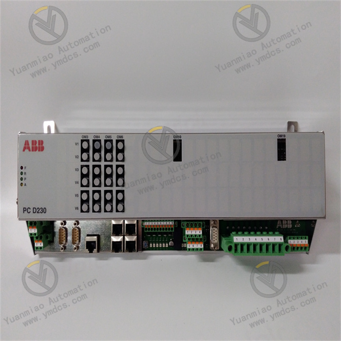
Description
Redundant system configuration (1) : Install software ◆ Install RSLogix5000/Studio5000 software, pay attention to the version, RSLinx Classic software will be automatically installed. ◆ If use ControlNet architecture, install RSNetWorx for ControlNet software. ◆ Install redundant firmware packages, ControlFlash V14 or above or ControlFlash Plus tools ◆ Install the redundant configuration tool RMCT (2) : Install hardware ◆ Install the power module, processor, communication module, and redundant module into the rack. ◆ In two racks, install the same module in the same slot. It is recommended that redundant modules be placed close to the processor. ◆ ControlNet Communication module nodes are set through DIP switches. ◆ Optical fiber connection for redundant modules, no sequence requirement for optical ports. ◆ Connect the power supply to the power module. (3) Establish a connection with the computer ◆ Power on two racks. ◆ Connect the processor to the computer using a USB cable, and you can see the rack and all the modules on the rack in RSLinx Classic. ◆ Set IP address for Ethernet module in RSLinx Classic, changed to static. You can also use BOOTP-DHCP to directly set the IP address for the Ethernet module. ◆ The IP addresses, subnet masks, and gateways of the corresponding Ethernet modules must be the same. ◆ Set up Ethernet/IP driver in RSLinx Classic, you can see the rack and all the modules on the rack through Ethernet. (4) : Firmware refresh ◆ Use the ControlFlash or ControlFlash Plus tools to refresh the modules in the rack. ◆ The version to be updated depends on the Release Notes of the firmware package. ◆ Brush on two racks respectively. ◆ The processor key switch is in REM mode. (5) : Network configuration Ethernet/IP ◆ Star topology, the Ethernet module is connected to the switch. ◆ Ring topology: Set the ring network manager, connect all DLR ring network nodes, view the ring network status in RSLinx Classic. ◆ Set Ethernet routes in RSLinx Classic (6) : Redundant module configuration ◆ Basic use No redundant modules are required. ◆ You are advised to use RMCT to set the redundant module time.
A gate driver is a power amplifier that accepts low-power input from the controller IC and generates an appropriate high-current gate drive for the power device. With the increasing demand for power electronic devices, the design and performance of gate driver circuits are becoming more and more important. Power semiconductor devices are the core of modern power electronic systems. These systems utilize many gated semiconductor devices such as common transistors, FETs, BJTS, MOSFETs, IGBTs, etc., as switching elements in switched mode power supplies (SMPS), general purpose power supplies (UPS), and motor drivers. Modern technological developments in power electronics usually follow the development of power semiconductor devices. Power level requirements and switching frequencies are increasing in the power electronics industry. Metal-oxide-semiconductor field-effect transistors (MOSFETs) and insulated-gate bipolar transistors (IGBTs) are two of the most popular and efficient semiconductor devices for medium to high power switching power supplies in most applications. The gate of a MOSFET or IGBT is the electrically isolated control terminal for each device. The other terminals of these devices are the source and drain or the emitter and collector. In order to operate a MOSFET/IGBT, it is usually necessary to apply a voltage to the gate relative to the device source/emitter. In order to drive these switching devices on, the gate terminals must be set to positive with respect to their source/emitter. The switching behavior of power devices is affected by parasitic capacitance between the three terminals, namely, gate to source (CGS), gate to drain (CGD), and drain-source to source (CDS), which is usually non-linear and a function of the bias voltage. Charging the gate capacitor causes the power device to be on and allows current to flow between its drain and source extremes, while when discharged, it shuts down the device and blocks large voltages at the drain and source extremes. The gate voltage of a power device does not increase unless its gate input capacitor is charged and the power device reaches the gate threshold voltage (V thousand) at its gate voltage. A fifth-generation kilopower device is defined as the minimum gate bias required to create an on-path between its source and drain regions. For operating a power device as a switch, a voltage sufficient to be greater than V kilowatts should be applied between the gate and source/emitter terminals.

The company focuses on DCS, PLC, robot, large servo four systems
The main products are various modules/cards, controllers, touch screens, servo drivers
Company advantage: Supply imported original products, professional production of spare parts
One year warranty, fast delivery time, complete supply !!!
① 24 hours email response (12 hours);
② For shipment outside Asia, please contact the seller.
【 Disclaimer 】 We sell new products and discontinued products, independent channels to buy such special products. Guizhou Yuanmiao Automation Equipment Co., Ltd. is not an authorized distributor, dealer or representative of the products featured on this website. All product names/product images, trademarks, brands and microlabels used on this Website are the property of their respective owners. Descriptions, depictions or sales of products with such names/images, trademarks, brands and logos are for identification purposes only and do not imply any association or authorization with any rights holder. This article is from the official website of Guizhou Yuanmiao Automation Equipment Co., LTD. Please attach this link:http://www.ymdcs.com/Allen-Bradley/