Description
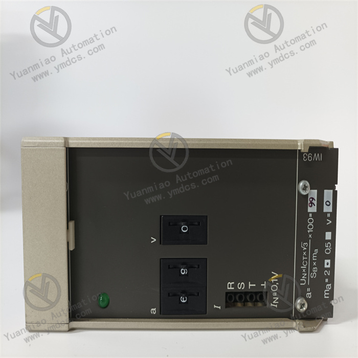
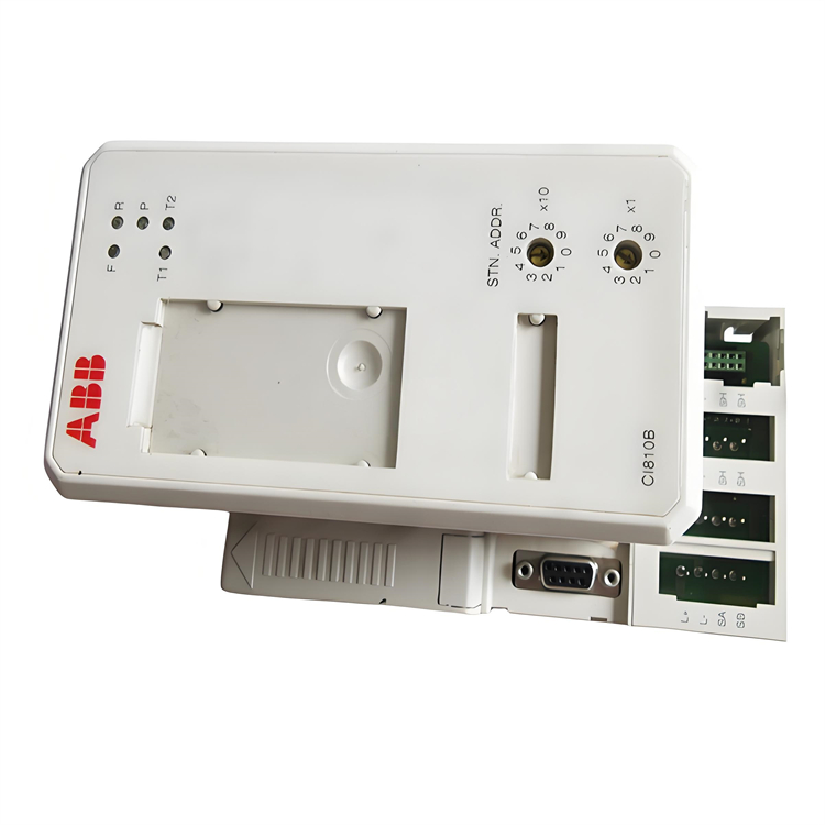
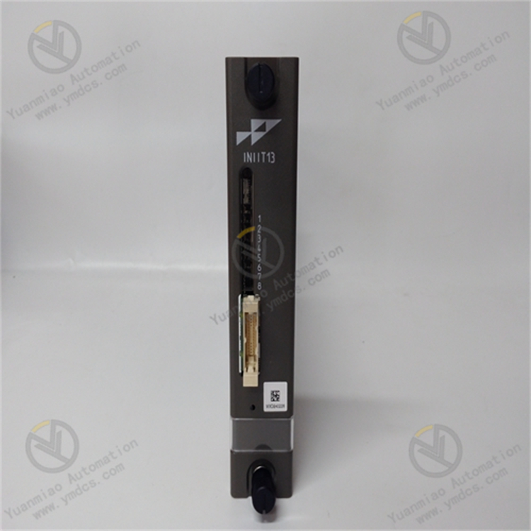
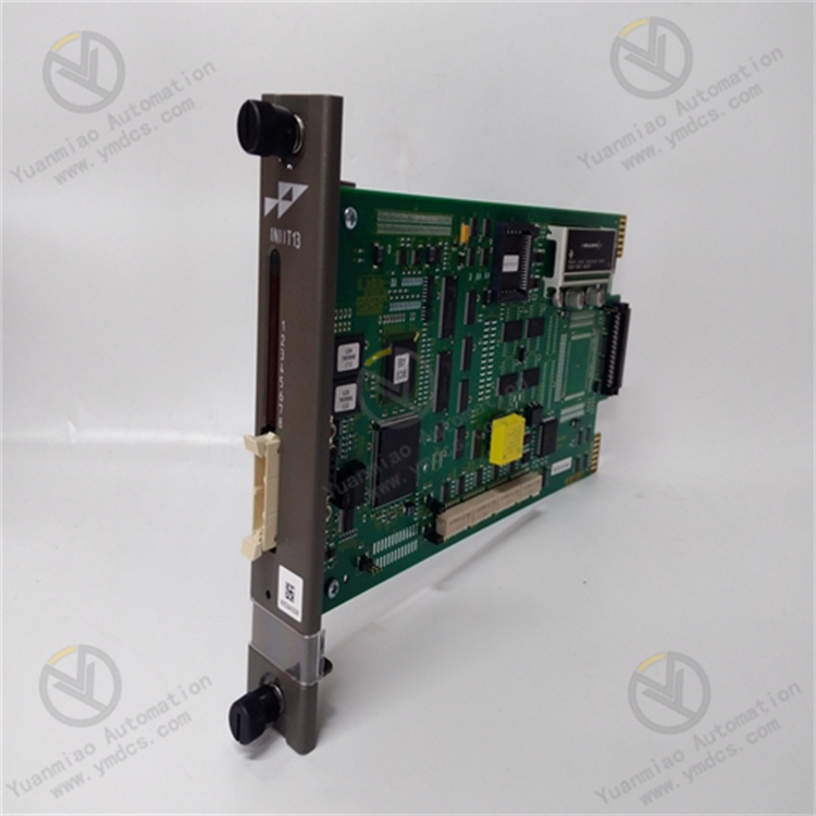
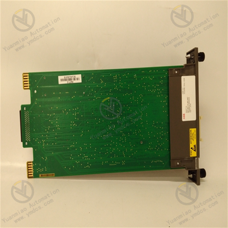
Bailey INIIT13
The ABB Bailey INIIT13 is an industrial control module in the ABB Ability System 800xA distributed control system (DCS). It uses Structured Text (ST) programming language and can implement complex control logic and automation sequences in various industrial applications.
Key Features
- Programming Standard: Supports the IEC 61131-3 ST programming standard, enabling engineers to use mature and widely accepted programming languages for control applications.
- Modular Design: Allows flexible configuration and expansion of control functions to meet specific application requirements.
- High Performance: Provides high-speed processing capabilities to ensure timely execution of complex control algorithms.
- Hot-Swap Design: Supports hot-swapping, enabling easy replacement or addition of control modules without interrupting system operation.
- Robust Structure: Designed for harsh industrial environments, capable of withstanding extreme temperatures, vibrations, and electromagnetic interference.
Technical Parameters
- Processor: High-performance industrial processor.
- Memory: Features RAM and flash memory for program storage and data processing.
- Communication Interfaces: Includes Ethernet, PROFIBUS DP, and PROFINET.
- Operating Voltage: 24VDC.
- Operating Temperature: -25°C to +55°C.
- Operating Humidity: 0% to 95% (non-condensing).
Application Areas
- Process Control: Used to implement complex control algorithms for regulating process parameters such as temperature, pressure, flow, and liquid level.
- Manufacturing: Controls and coordinates complex production processes in manufacturing environments, including machine sequencing, robot control, and quality assurance.
- Building Automation: Manages and optimizes energy consumption, lighting systems, and HVAC systems.
- Infrastructure Management: Controls and monitors critical infrastructure components such as power distribution networks, water treatment plants, and transportation systems.
Common Faults and Solutions for ABB Bailey INIIT13
I. Communication Faults
- Module Fails to Communicate with the Host/Supervisory Computer
- Check Power Supply: Measure the module's supply voltage with a multimeter to ensure it meets specifications (e.g., 24V DC ±10%). Restart the module and observe status indicators.
- Troubleshoot Wiring:
- Calibrate Parameters:
- Upgrade Firmware/Software: Download the latest firmware from the ABB official website and upgrade according to the manual; confirm host software version supports the module model.
- Replace Module: If the above steps fail, hardware failure is likely; replace with the same model for testing.
- Replug communication cables, check terminal tightness, and test with replacement cables.
- For RS-485 networks, confirm correct termination resistor (120Ω) installation and ensure network topology complies with standards (e.g., changing from star to bus topology).
- Check module communication parameters via configuration software (e.g., the engineer station of the Bailey INFI 90 system) to ensure consistency with the host.
- For Ethernet communication, check for IP address conflicts with the local area network and attempt to ping the module's IP.
- Power not connected or voltage Anomaly (e.g., input voltage outside the rated range).
- Loose, damaged, or incorrectly wired communication cables (e.g., reversed RS-485 polarity).
- Mismatched communication parameter settings (e.g., baud rate, data bits, parity, IP address conflicts).
- Outdated module firmware or incompatibility with host software.
- Hardware damage (e.g., faulty communication chip).
- Possible Causes:
- Solutions:
- Abnormal Communication Data/Packet Loss
- Anti-Interference Measures:
- Reduce Communication Speed: Lower the baud rate in the configuration software (e.g., from 115200 to 9600) and observe stability.
- Optimize Data Configuration: Reduce single-transmission data volume or increase communication interval time to avoid buffer overload.
- Use shielded twisted-pair cables for communication lines, keep away from power cables, and ground the shield on a single end.
- Add signal repeaters (e.g., RS-485 repeaters) to extend transmission distance.
- Electromagnetic interference (e.g., high-power equipment near communication lines).
- Excessive communication speed causing signal attenuation (especially for long-distance transmission).
- Overflow of the module or host's communication buffer (e.g., data volume exceeding processing capacity).
- Possible Causes:
- Solutions:
II. Power Supply Faults
- No Power to Module/Power Indicator Off
- Check External Power Supply: Use a multimeter to confirm normal power output and replace faulty power supplies or fuses.
- Clean and Reconnect: Disassemble power terminals, clean oxidation, and reconnect with correct polarity (+/- markings).
- Test Internal Circuitry: If power input is normal but the module is unresponsive, the internal power module may be damaged; return for repair or replace.
- External power failure (e.g., damaged switching power supply, blown fuse).
- Loose module power interface, oxidized terminals, or internal fuse burnout.
- Reversed power input polarity (for DC-powered modules only).
- Possible Causes:
- Solutions:
- Flickering/Abnormal Power Indicator
- Measure Power Quality: Use an oscilloscope to detect power ripple and replace with a stable power supply or add filter capacitors.
- Troubleshoot Load Equipment: Disconnect all external loads (e.g., sensors, actuators) and reconnect them step-by-step to locate the short circuit point. Power on again after repair.
- Unstable power voltage (e.g., excessive ripple).
- Internal overload or short circuit (e.g., high-voltage misconnection at I/O interfaces causing overload).
- Possible Causes:
- Solutions:
III. Hardware and Status Indicator Faults
- Abnormal Module Status Indicators (e.g., ERROR Light On Constantly)
- Restart and Reset: Power off and restart the module; attempt to restore factory settings (if requiring specialized tools or software).
- Check Configuration Files: Redownload correct configuration programs via the engineer station to ensure parameter validity (e.g., range, unit settings).
- Improve Heat Dissipation: Ensure the module is installed in a well-ventilated cabinet, clean surface dust, and add fans if necessary.
- Replace Memory/Module: Frequent memory faults may indicate hardware defects; contact ABB technical support.
- Firmware operation errors or program configuration errors (e.g., parameters exceeding limits).
- Internal memory faults (e.g., abnormal Flash chip).
- Overheating due to poor heat dissipation (e.g., inadequate ventilation in the installation environment).
- Possible Causes:
- Solutions:
- Unresponsive/Abnormal I/O Interfaces
- Reconnect Modules: Check bus connector tightness and try replacing connectors or slots.
- Calibrate Signal Types: Confirm I/O module configuration matches actual signals (e.g., setting AI modules to 4-20mA or 0-10V) and reconfigure channel parameters.
- Isolation Testing: Disconnect external equipment and test module channels with a signal generator. Replace or repair modules if anomalies are detected.
- Loose connection between I/O module and main module (e.g., unplugged bus connector).
- Mismatched signal types (e.g., digital signals fed into analog input modules).
- Module channel damage due to external equipment faults (e.g., overvoltage breakdown).
- Possible Causes:
- Solutions:

IV. Software and Configuration Faults
- Configuration Software Fails to Recognize Module
- Install/Update Drivers: Download corresponding module drivers from the ABB website and retry after restarting the software.
- Check Device Addresses: Set a unique station number via module DIP switches or software (e.g., PROFIBUS slave address) to avoid duplicates.
- Reconfigure Projects: Delete existing modules in the configuration software, rescan, and add the correct model and parameters.
- Uninstalled or incompatible driver versions.
- Conflicting module address settings (e.g., multiple modules using the same station number).
- Incorrect module model addition in the software project.
- Possible Causes:
- Solutions:
- Program Download Failure or Abnormal Operation
- Debug Programs: Use the software's online diagnostic functions to check for syntax errors and debug logic step-by-step to avoid infinite loops or resource conflicts.
- Optimize Programs: Remove redundant code, split complex function blocks, and ensure program size does not exceed module memory limits.
- Program logic errors (e.g., syntax errors, loop deadlocks).
- Insufficient module memory (e.g., programs exceeding storage capacity).
- Possible Causes:
- Solutions:
V. Preventive Maintenance Recommendations
- Regular Inspections:
- Check module indicator status monthly and record abnormal alarm information.
- Clean module surfaces quarterly and inspect terminal tightness.
- Data Backup:
- Regularly backup module configuration files and programs to offline media (e.g., USB drives, hard disks) to prevent data loss during firmware upgrades or hardware failures.
- Environmental Management:
- Ensure installation temperature is within the module's allowable range (typically 0°C–50°C) and humidity is below 90% (non-condensing).
- Avoid strong vibrations, impacts, and corrosive gases.