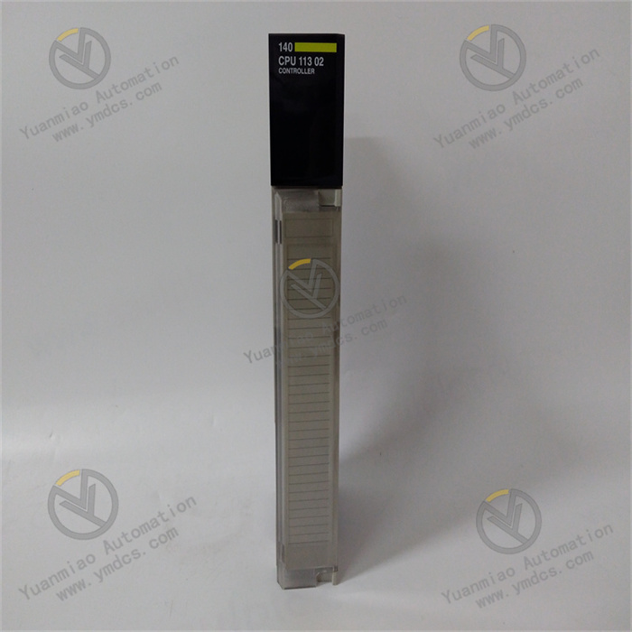
Description
In the design of DC motor drive circuit, the following points are mainly considered: Function: Is the motor unidirectional or bidirectional? Do you need speed regulation? For unidirectional motor drive, as long as a high-power transistor or field effect tube or relay directly drive the motor, when the motor needs to be bidirectional rotation, you can use the H-bridge circuit composed of 4 power components or use a double-pole double-throw relay. If speed regulation is not required, just use a relay; However, if speed regulation is required, switching elements such as triode and field effect tube can be used to achieve PWM (pulse width modulation) speed regulation. Performance: For PWM speed control motor drive circuit, there are mainly the following performance indicators. 1) Output current and voltage range, which determines how much power the circuit can drive the motor. 2) Efficiency, high efficiency not only means saving power, but also reduces the heat of the drive circuit. To improve the efficiency of the circuit, you can start with ensuring the switching status of the power device and preventing common-mode conduction (a problem that may occur in H-bridge or push-pull circuits, that is, two power devices are switched on at the same time to short-circuit the power supply). 3) Influence on the control input. The power circuit should have good signal isolation to its input to prevent high voltage and high current from entering the main control circuit, which can be isolated by high input impedance or photoelectric coupler. 4) Influence on power supply. The common-mode conduction can cause the instantaneous drop of the power supply voltage and cause the pollution of the high-frequency power supply. Large currents may cause ground potential to float. 5) Reliability. The motor drive circuit should be as far as possible, no matter what kind of control signal, what kind of passive load, the circuit is safe.
Wiring instructions: 1. Power interface: Module power supply, input voltage 5V to 35V. 2. Dual motor interface: respectively connected to both ends of the motor. 3. Single-chip interface: IN1~IN4 pairs should be connected to single-chip IO port to control motor 1~ motor 2 in turn. 4.5V power input: A set of logic levels. Product parameters: Power input voltage range: MAX power: 50W (one L298N MAX is 25W) Driving peak current: 4A Power supply range of logic part: +5V~+7 (5V is used for recommended logic voltage on the board) Logical part power supply current: 0~36mA Storage temperature: -20 ° C -135 ° C Control input voltage range: low level -0.3V~1.5V. High level 2.3V~ supply voltage
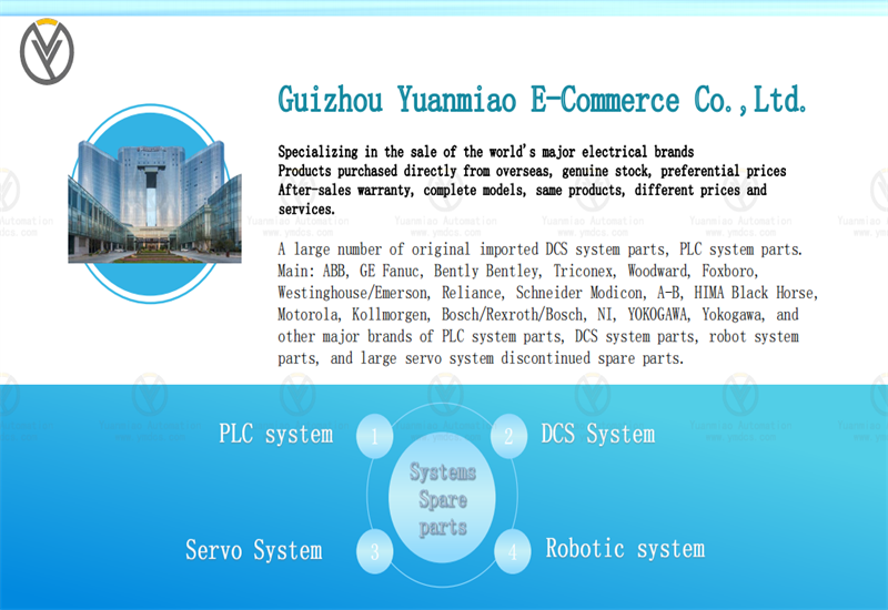
The company focuses on DCS, PLC, robot, large servo four systems
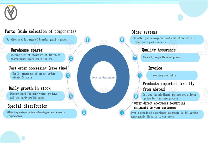
The main products are various modules/cards, controllers, touch screens, servo drivers Company advantage: Supply imported original products, professional production of spare parts One year warranty, fast delivery time, complete supply !!! ① 24 hours email response (12 hours); ② For shipment outside Asia, please contact the seller.
【 Disclaimer 】 We sell new products and discontinued products, independent channels to buy such special products. Guizhou Yuanmiao Automation Equipment Co., Ltd. is not an authorized distributor, dealer or representative of the products featured on this website. All product names/product images, trademarks, brands and microlabels used on this Website are the property of their respective owners. Descriptions, depictions or sales of products with such names/images, trademarks, brands and logos are for identification purposes only and do not imply any association or authorization with any rights holder. This article is from the official website of Guizhou Yuanmiao Automation Equipment Co., LTD. Please attach this link:http://www.ymdcs.com/ABB/


