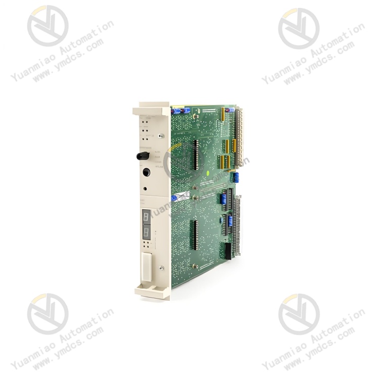
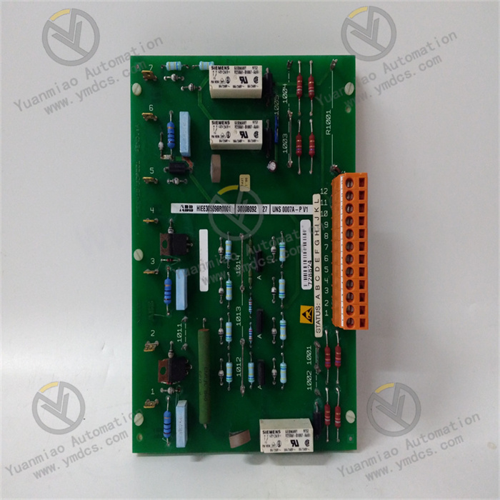
Description
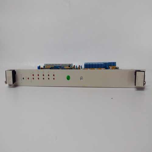
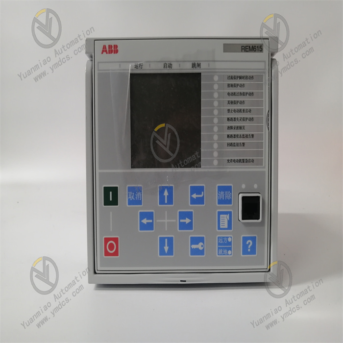
Relay is an automatic switch element with isolation function, which is widely used in remote control, telemetry, communication, automatic control, mechatronics and power electronic equipment, and is one of the most important control components. Relays generally have an induction mechanism (input part) that can reflect certain input variables (such as current, voltage, power, impedance, frequency, temperature, pressure, speed, light, etc.); There is an actuator (output part) that can realize “on” and “off” control of the controlled circuit; Between the input part and the output part of the relay, there is an intermediate mechanism (drive part) for coupling and isolating the input, functional processing and driving the output part. As a control element, in summary, the relay has the following functions: (1) Expand the control range: For example, when the control signal of the multi-contact relay reaches a certain value, it can be changed, broken, and connected to the multi-circuit at the same time according to different forms of the contact group. (2) Amplification: For example, sensitive relays, intermediate relays, etc., can control a large power circuit with a very small control amount. (3) Integrated signal: For example, when multiple control signals are input into multi-winding relays in the specified form, the predetermined control effect is achieved through comparative integration. (4) Automatic, remote control, monitoring: for example, the relay on the automatic device, together with other electrical appliances, can form a program control line, so as to achieve automatic operation.

① Rated working voltage: refers to the voltage required by the coil when the relay is working normally. Depending on the type of relay, it can be AC voltage or DC voltage.
② DC resistance: refers to the DC resistance of the coil in the relay, which can be measured by a multimeter.
③ Suction current: refers to the minimum current that the relay can produce suction action. In normal use, the given current must be slightly greater than the draw current for the relay to work stably. For the working voltage added to the coil, generally do not exceed 1.5 times the rated working voltage, otherwise it will produce a large current and burn the coil.
④ Release current: refers to the maximum current generated by the relay release action. When the current in the draw state of the relay is reduced to a certain degree, the relay will return to the unpowered release state, and the current is far less than the draw current.
⑤ Contact switching voltage and current: refers to the voltage and current that the relay allows to load. It determines the size of the voltage and current that the relay can control, and cannot exceed this value when used, otherwise it is easy to damage the contact of the relay.

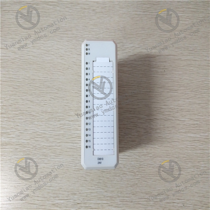
PLC analog input module (analog input module), also known as A/D module, converts the continuous analog signal generated by the sensor detection in the field into the digital quantity that the PLC CPU can receive, generally 12-bit binary number, the more digital quantity modules, the higher the resolution. PLC analog output module. The analog output module, also known as D/A module, converts the digital quantity sent by the PLC CPU to the analog output module into the analog quantity (voltage or current) that can be received by the external device. The digital signal received by the analog output module is generally 12-bit binary number, and the more digital quantity modules, the higher the resolution. The digital module is to detect the state of the external switching input. Digital input and output signal is the switching signal, 0 or 1, analog signal, there are two, voltage or current signal, generally the signal transmitted by the transmitter, such as the pressure transformer to detect the pressure of the water pipe, it will output an analog signal 4-20ma or 0-10V signal to the PLC, PLC for data processing, This is the difference between a digital input module and an analog input module.
In the input sampling phase, the PLC successively reads all input status and data by scanning and stores them in the corresponding cell in the I/O image area. After the end of the input sampling, the user program execution and output refresh phase. In both phases, even if the input state and data change, the state and data of the corresponding unit in the I/O map area will not change. Therefore, if the input is a pulse signal, the width of the pulse signal must be greater than one scan cycle to ensure that the input can be read in any case.
The acquisition of the switching quantity is realized through the PLC input module, which is generally a DC 24V input. The PLC provides a common point, positive or negative, and then the common point is connected to the limit switch and other devices. When the limit is closed, the path is formed and the signal is introduced into the PLC input point. Specifically why the input point to power inside the state is on, is the function of PLC itself, you do not need to tube.
Through the analog module, A/D (analog/digital) module, the external weight signal, temperature signal, pressure signal can be introduced, A/D module can accept the signal is 0-10V, 0-5V, -5-5V voltage signal and 0-20MA, 4-20MA current signal. If the signal obtained by the terminal acquisition module is not these standard signals, but also through the transmitter conversion, after the standard signal enters the A/D module, it will be converted by A/D into a number, the specific range is different PLC is not the same, these converted digital quantities, can be used by the program, conversion, processing, and finally get the required data displayed.
The company focuses on DCS, PLC, robot, large servo four systems
The main products are various modules/cards, controllers, touch screens, servo drivers
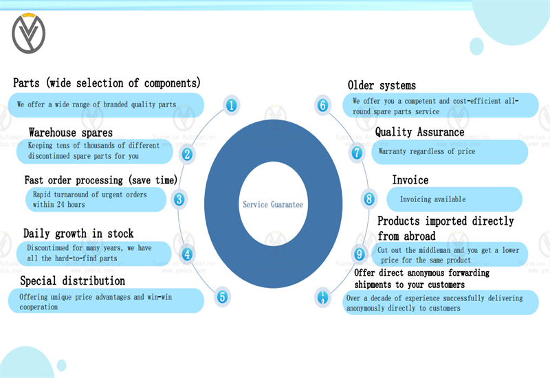
Company advantage: Supply imported original products, professional production of spare parts
One year warranty, fast delivery time, complete supply !!!
① 24 hours email response (12 hours);
② For shipment outside Asia, please contact the seller.
【 Disclaimer 】 We sell new products and discontinued products, independent channels to buy such special products. Guizhou Yuanmiao Automation Equipment Co., Ltd. is not an authorized distributor, dealer or representative of the products featured on this website. All product names/product images, trademarks, brands and microlabels used on this Website are the property of their respective owners. Descriptions, depictions or sales of products with such names/images, trademarks, brands and logos are for identification purposes only and do not imply any association or authorization with any rights holder. This article is from the official website of Guizhou Yuanmiao Automation Equipment Co., LTD. Please attach this link:http://www.ymdcs.com/other_brand/


