Description
1. Overview
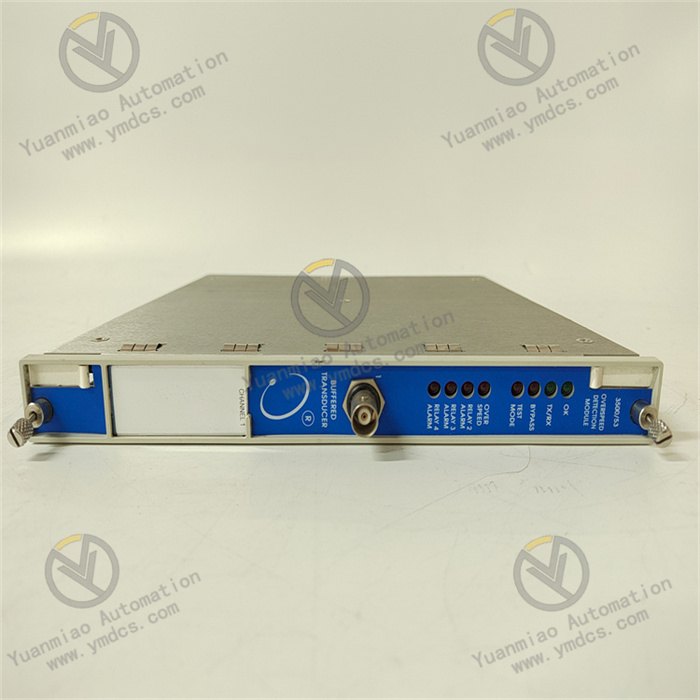
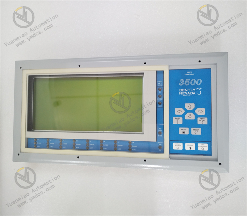
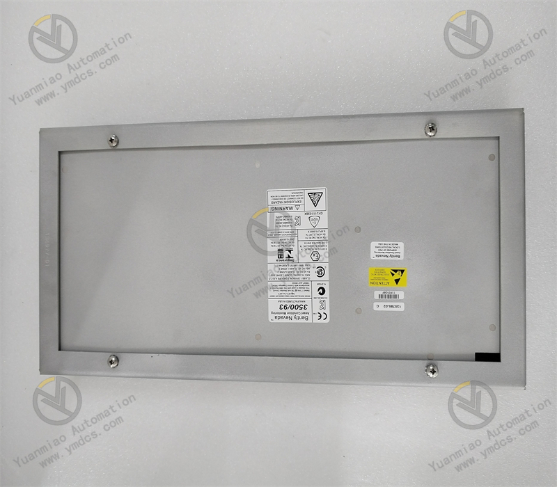
Bently Nevada 3500/93 135785‑02 is a dedicated system display module for the Baker Hughes Bently Nevada 3500 series machinery protection monitoring system. As the core human‑machine‑interaction unit of the 3500 rack, it serves as the key carrier for data visualization, parameter configuration, condition diagnosis and on‑site maintenance of the complete unit condition‑monitoring and protection system. This industrial‑standard upgraded model is fully compatible with the full range of 3500 rack monitoring systems. It seamlessly cooperates with various monitoring modules, communication modules and power‑supply modules of the 3500 system, and is widely deployed in condition‑monitoring and protection systems for large rotating machinery such as steam turbines, centrifugal compressors, blowers, pumps and electric motors.
Adopting an industrial high‑resolution TFT‑LCD architecture and proprietary Bently Nevada system‑bus communication protocol, the 3500/93 display module delivers core capabilities including multi‑channel synchronous data refresh, real‑time status display, local parameter configuration, pop‑up fault alarms and system self‑diagnosis. Different from conventional remote HMI access, it supports on‑site cabinet‑local operation and status inspection. System parameter verification, channel status review, alarm inquiry and basic configuration modification can be performed without external industrial‑control devices. Featuring wide‑temperature operation, high anti‑interference performance, stable communication and industrial‑grade conformal coating protection, it fits harsh cabinet environments in thermal‑power, chemical, oil‑gas and metallurgical industries. It is an essential core module for on‑site maintenance, fault troubleshooting and system commissioning of the 3500 monitoring system.
2. Functions and Features
2.1 Core Functions
Real‑time Full‑system Channel Data Visualization: Supports synchronous acquisition and display of up to 32 monitoring channels of the 3500 rack. It presents all unit monitoring parameters including shaft vibration, shaft displacement, temperature, rotational speed, differential expansion and shaft eccentricity with fast data refresh and accurate synchronization with real‑time system status.
Local System Configuration and Parameter Setup: No host‑side software required. Channel parameters, alert thresholds, trip thresholds, filter settings and range parameters can be viewed and modified directly via front‑panel keys and display. It facilitates fast field commissioning, parameter verification and technical‑retrofit adaptation.
Multi‑level Alarm and Pop‑up Fault Prompting: Implements three‑level status identification: Normal, Alert and Danger‑Trip. Pop‑up alarms are automatically triggered upon channel anomalies, parameter over‑range, module faults and communication failures. Fault types, affected channels and alarm severity are clearly distinguished to help maintenance personnel rapidly locate hazards.
Full‑rack System Self‑diagnosis Monitoring: Continuously monitors rack power‑supply health, module online status, backplane‑bus communication, loop faults and hardware abnormalities. It provides full coverage of monitoring‑chain health and prevents hidden failures from being overlooked.
Historical Alarm and Fault‑log Query: Built‑in local fault storage enables retrieval of recent historical alarms, over‑range events and system anomaly logs, delivering local data support for unit fault tracing, trend analysis and hazard review.
Standardized System‑bus Compatibility: Natively interfaces with the 3500 internal high‑speed backplane bus for low‑latency, high‑synchronization data exchange with all monitoring, communication and power‑supply modules in the rack, ensuring data consistency and reliable system coordination.
24/7 Industrial‑grade Continuous Operation: Designed for 7×24‑hour cabinet‑mounted service. It withstands temperature cycling, dust, mild humidity and electromagnetic interference, and maintains stable human‑machine‑interface and maintenance functions over long‑term operation.
2.2 Product Characteristics
High‑definition Industrial Display: Equipped with a 10.4‑inch industrial TFT‑LCD at 800×600 resolution. Wide‑viewing‑angle and high‑brightness design ensures clear rendering of values, curves and status pages under both bright and dim cabinet‑room conditions without ghosting or distortion.
High‑speed Data Refresh: 250 ms overall data refresh cycle for synchronized multi‑channel updates without stalling or lag, enabling capture of transient parameter fluctuations and short‑duration over‑range events.
Broad‑temperature Industrial Robustness: Core circuits and display components are industrial‑grade wide‑temperature screened. No black‑screen at low temperature and no screen distortion at high temperature; ultra‑low thermal drift guarantees stable display and communication across operating conditions.
PCB Conformal Coating for Corrosion Protection: Printed‑circuit boards are coated with polyimide conformal coating for resistance to salt mist, mould and corrosion. It extends service life in humid, corrosive cabinet environments typical of chemical and oil‑gas plants.
High‑immunity Stable Communication: Dedicated rack‑bus architecture provides strong electromagnetic‑interference resistance against noise from cabinet power supplies, variable‑frequency drives and relays. It avoids communication drop‑outs and data corruption during long‑term service.
Lightweight Modular Hot‑swap Design: Standard 3500‑rack form‑factor supports hot‑swap removal and insertion. Module replacement, maintenance and expansion can be performed without rack power‑off, minimizing maintenance effort and system‑downtime risk.
Low‑power Long‑duration Operation: Optimized power‑consumption design yields low heat generation. Continuous long‑run operation is free of overheating‑induced crash, black‑screen or reboot faults, meeting requirements for permanent online unit monitoring.
3. Specifications
| Item | Specifications |
|---|---|
| Model | 3500/93 135785‑02 |
| Product Type | 3500‑series System Display & Human‑Machine‑Interface Module |
| Brand & Manufacturer | Bently Nevada (Baker Hughes) |
| Compatible System | Bently Nevada 3500 full‑range machinery‑protection monitoring rack system |
| Display Panel | 10.4‑inch industrial TFT‑LCD |
| Resolution | 800×600 |
| Maximum Channel Capacity | 32 channels simultaneous display |
| Data Refresh Cycle | 250 ms |
| Communication Interface | 3500 proprietary internal high‑speed backplane bus |
| Power Supply | Backplane‑shared rack power feed |
| Operating Voltage | 24~48 VDC wide‑range input |
| Operating Temperature | ‑55 ℃ ~ +125 ℃ (stable range for communication and circuitry) |
| Storage Temperature | ‑40 ℃ ~ +85 ℃ |
| Ambient Humidity | 5%‑95% RH, non‑condensing |
| Protection Technology | Polyimide PCB conformal coating, dust‑proof & moisture‑proof mechanical construction |
| Performance Features | High‑definition display, fast refresh, wide‑temperature stability, high EMI immunity, local configuration, self‑diagnosis, hot‑swap maintainability |
4. Operating Principle
The Bently Nevada 3500/93 135785‑02 system‑display module operates based on real‑time data exchange over the 3500 rack internal backplane bus. As the local human‑machine‑interaction core of the monitoring system, it implements the closed‑loop of on‑site maintenance via overall data aggregation, visual output, parameter configuration and fault‑diagnosis feedback.
During operation, all monitoring and communication modules inside the 3500 rack transmit real‑time data including vibration, displacement, temperature, rotational speed, alarm status and hardware health to the 3500/93 via the high‑speed backplane bus. The on‑board main‑control unit aggregates, parses, processes and categorizes multi‑channel data while filtering bus noise and invalid samples to guarantee full consistency with backend monitoring logic.
Processed standardized data are rendered on the high‑resolution LCD as numerical values, status indicators and pop‑up alarms. Meanwhile front‑panel keypad inputs are responded to execute local operations: parameter modification, threshold setup, channel enable/disable, fault‑log retrieval and system self‑test. When measured parameters cross alert or trip thresholds, or hardware events such as module off‑line, bus anomaly or power‑supply failure occur, the module activates audible‑visual hints and pop‑up alarms to report fault severity and location.
All locally‑applied configuration parameters are written in real time to the rack main controller and synchronize bi‑directionally with remote host HMI, eliminating parameter mismatch and data desynchronization. Supported by wide‑temperature circuitry and conformal‑coating protection, the module reliably performs visualization and local‑maintenance functions under complex cabinet conditions and ensures serviceability and dependability of the complete 3500 protection‑monitoring system.
5. Application Scenarios
On‑site Local Status Inspection for 3500 Cabinets: Used for field walk‑down of 3500 monitoring cabinets serving steam turbines and compressors in thermal‑power, chemical and oil‑gas facilities. Full‑channel vibration, displacement, temperature and alarm status are accessible without host‑side equipment for rapid on‑site condition assessment.
On‑site System Commissioning and Parameter Configuration: Suited for new‑unit commissioning, unit retrofits, measuring‑point expansion and parameter optimization. Alarm thresholds, ranges, filter settings and channel enables can be configured and verified locally to simplify commissioning and reduce maintenance costs.
Rapid Equipment Fault Localization & Troubleshooting: Upon unit anomalies, parameter over‑range or system alarms, pop‑up alerts and historical fault logs support fast identification of affected channels, fault types and event timestamps for expedited response and root‑cause tracing.
Local Monitoring Redundancy for Unattended Control Rooms: Acts as local backup monitoring when remote HMI fails or network communication is lost. Critical unit data and alarm functions remain available locally to eliminate monitoring blind spots.
Retrofit & Replacement for Legacy 3500 Systems: Drop‑in replacement for aged display modules suffering from screen distortion, black‑screen or communication loss. It is fully compatible with existing rack architecture and parameter logic; no rewiring or rack modification is required to restore local visualization.
Long‑term Stable Operation in Harsh Industrial Cabinets: Wide‑temperature tolerance, corrosion resistance and high noise immunity enable reliable deployment in high‑temperature, humid, dusty and EMI‑intensive cabinet environments for 7×24‑hour continuous monitoring and maintenance.
6. Common Faults and Troubleshooting
6.1 Black screen, no display, unit fails to power‑up
Root Causes: Abnormal or unstable backplane rack power supply; aged or damaged module power circuit; poor module contact and oxidized backplane‑slot contacts; complete hardware failure of the module.
Solutions: Measure rack supply voltage and verify health of rack power‑supply modules. Power off, extract the display module, clean gold‑finger contacts and backplane‑slot oxidation, then re‑seat and lock firmly. Reboot the rack and retest. If no display persists despite good power and contact, replace with a new module.
6.2 Screen distortion, flickering, garbled graphics, missing characters
Root Causes: Loose internal display‑panel cabling; degraded display‑driver circuitry; excessive cabinet ambient temperature; program stall or corrupted data cache after long‑run operation.
Solutions: Power off and re‑secure internal display connections. Clear cabinet air‑vent blockages to improve thermal dissipation and lower cabinet temperature. Perform system reset to clear cache anomalies. Replace module if symptoms recur.
6.3 Frozen data, screen stalling, static parameter readings
Root Causes: Abnormal system‑bus communication and interrupted data transfer; module firmware lock‑up; degraded backplane‑bus contact; single‑channel fault causing overall synchronization stall.
Solutions: Review online status of all rack modules and isolate off‑line units. Reboot rack bus and display‑module firmware. Inspect backplane‑bus integrity. Replace display module if stalling remains after elimination of system‑link failures.
6.4 Local configuration unavailable, keypad unresponsive
Root Causes: Aged and degraded front‑panel keypad contacts; firmware anomaly or access‑permission lock; bus‑communication failure preventing command delivery.
Solutions: Unlock system access permissions and clear parameter‑lock status. Reboot module to restore firmware execution. Clean keypad contacts and verify keypad hardware. Replace module if local‑operation functions cannot be recovered.
6.5 Missing alarm pop‑ups, faulty status indication
Root Causes: Incorrect system‑alarm‑logic configuration; defective module alarm‑storage and prompting functions; bus‑synchronization delay and lost alarm events; firmware‑version mismatch between module and rack system.
Solutions: Verify system‑alarm logic and pop‑up‑message configuration settings. Align firmware revisions of rack and display module. Restart bus‑communication links. Replace module if alarm‑prompting failure persists after configuration correction.
6.6 Intermittent disconnection, sporadic data loss, occasional off‑line status
Root Causes: Loose module seating and poor backplane‑slot contact; cabinet‑vibration‑induced module displacement; unstable bus‑link performance; internal circuit ageing and reduced operating margin.
Solutions: Re‑insert and fasten module; apply anti‑loosening measures. Optimize cabinet wiring layout to mitigate vibration disturbance. Verify bus‑communication stability. Replace genuine OEM module if intermittent faults cannot be eliminated.