Description
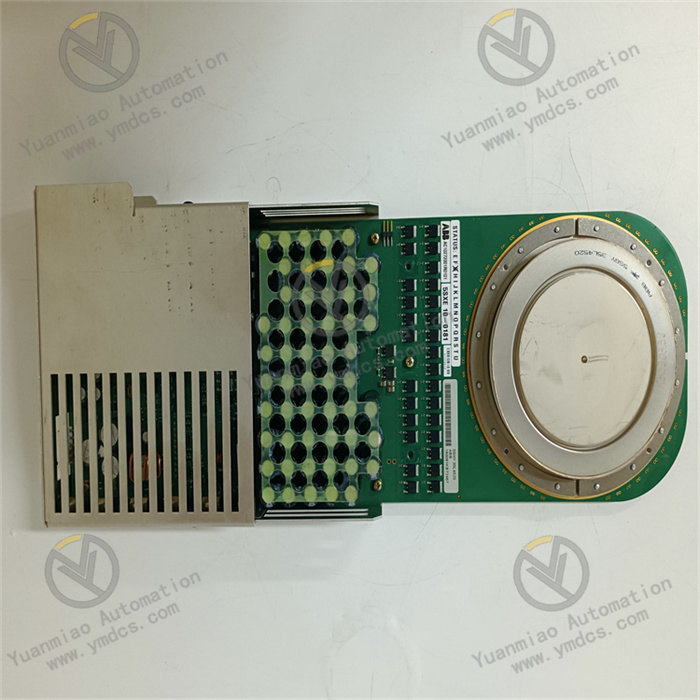
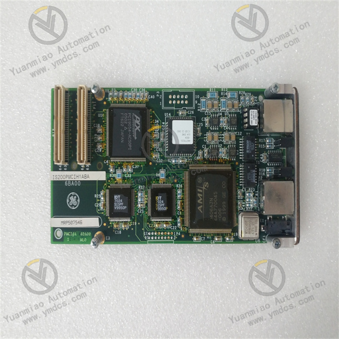
Part Number: IS200DSPXH1A
Manufacturer: General Electric
Series: EX2100
Product type: DSP Control Board
Operating speed: 60 MHz
ISBus Osc.: 80MHz
SRAM: 64Kx32 - 512Kx32
FLASH: 128Kx32 - 256Kx32
Hardware/Fuses: None
LED Light Indicators: 2 (Fault and Status)
Pin Quantity for Data Bus Function: 32
Power Supply Input: 5 V
Country of Manufacture: United States (USA)
Functional Description
IS200DSPXH1A is a Digital Signal Processor (DSP) Control Board developed by GE. It is a part of EX2100 excitation system. The DSPX is the primary controller for the Innovation Series drives' bridge, motor regulator, and gating functions. It also controls the EX2100 Excitation Control's generator field control functions. The logic, processing, and interface functions are all provided by the board. The DSPX board contains a high-performance digital signal processor (DSP), standard memory components, and an application specific integrated circuit (ASIC) that handles custom logic functions. It is the primary controller in charge of bridge regulator functions. This DSPX board can also control generator field functions for the EX2100 series exciters. The board's primary function is to control the motor, bridge regulator, and gate functions for the Innovation Series drives. When connected to the Excitation Controller series, the board not only controls the motor and bridge regulators, but it also controls field control generator applications.

IS200DSPXH1A Standard Hardware Features
The DSPX's Digital Signal Processor (DSP) operates at a speed of 60 MHz. During normal operation, the DSP receives four external interrupts:
- Inner loop load pulse (INT1)
- Stack overflow (INT0)
- Two configurable inputs (INT2, INT3)
The DSPX board includes the following types of memory:
- FLASH memory is used for DSP boot images, code execution, and configurable item storage, as well as system history records.
- RAM is used for data storage and code execution.
- NVRAM is used for nonvolatile data storage.
Onboard Firmware
Flash memory stores onboard firmware. There are three major kinds:
- The boot loader is in charge of the power-on sequence and should not be reloaded in the field.
- The specific control functions for the drive or exciter product are defined by application code. This code is loaded via the exciter's Tool port, and configuration parameters are loaded via the toolbox. The Unit Data Highway is used to load exciter parameters.
- If applicable, drive parameters are loaded to ACL_ via serial port, ISBus, or Ethernet.
I/O Connections
- The P1 connector provides memory mapped process bus address space as well as four chip select signals to support bridge and customer input/output (I/O) interfaces. It also includes controls for a standard UART serial interface to a programmer board and a configuration tool. And two additional ISBus proprietary serial interfaces for ACL or local expansion functions.
- The P5 emulator port (on the board's front panel) connects to the TI emulator port. It includes a scan interface (similar to JTAG) for emulation and FLASH programming.
The P6 engineering monitor port (on the board's front panel) connects to the DSP synchronous serial port (at TTL levels) and allows connection to a GE engineering terminal only.
Board Replacement Procedure
- Ensure that the exciter has been deactivated.
- Open the control cabinet door and make sure the power indicators on the EPDM (if present) and EPSM power supplies, as well as the DSPX LEDs, are turned off.
- Disconnect the EISB front panel's six fiber-optic cables.
- Carefully remove the DSPX board and its attached EISB board from the control rack, as shown below:
- Loosen the screws near the ejector tabs at the top of the DSPX faceplate and the bottom of the EISB faceplate. (The screws in the faceplate are captive and should not be removed.)
- Remove the DSPX and EISB by pulling up on the ejector tabs.
- Gently pull both boards from the rack with both hands.
- Remove the EISB from the DSPX's bottom and connect it to the replacement DSPX.
- Insert the replacement DSPX and EISB boards into the appropriate rack slot.
- Begin seating the board by firmly pressing the top and bottom faceplates with your thumbs at the same time.
- Finish seating the module in the slot by tightening the screws at the top and bottom of the faceplate assembly alternately. To ensure that the module is seated squarely, tighten the screws evenly.
- Reconnect all communication cables that were removed with the old module.
Software Overview
- The exciter control code is executed by microprocessor-based controllers (ACLA and DSPX). The software is made up of modules (blocks) that work together to provide the necessary system functionality. Variables are stored in random-access memory, while block definitions and configuration parameters are stored in flash memory (RAM). Traditional analog controls are emulated by the exciter application software. It employs an open architecture system with a library of pre-configured software blocks from the toolbox.
- Individual blocks, such as logic gates, proportional integral (P.I.) regulators, function generators, and signal level detectors, perform specific functions.
- The control switches between two modes: generator voltage regulation (Auto Regulation) and direct control (voltage or current, depending upon the application). The control incorporates generator protection functions such as over and under-excitation limiting, power system stabilization, and V/Hz limiting.
- Using the toolbox, the blocks can be interrogated while the exciter is running. In operation, the dynamically changing I/O values of each block can be seen, which is useful during startup or troubleshooting.
Power Conversion Cabinet
- The Power Conversion cabinet houses the Power Conversion Module (PCM), the Exciter Gate Pulse Amplifier (EGPA) board, an alternating current circuit breaker, and a direct current circuit contactor. The PCM receives three-phase power from a PPT located outside of the exciter.
- The alternating current supply enters the cabinet via the ac circuit breaker (if one is provided) and is filtered by 3-phase line filters in the auxiliary cabinet.
The company focuses on DCS, PLC, robot, large servo four systems
The main products are various modules/cards, controllers, touch screens, servo drivers
Company advantage: Supply imported original products, professional production of spare parts
One year warranty, fast delivery time, complete supply !!!
① 24 hours email response (12 hours);
② For shipment outside Asia, please contact the seller.
Main brands include: ABB, Bailey, GE, FOXBORO, Invensys TRICONEX, Bentley BENTLY, A-B Rockwell, EMERSON EMERSON, B&R, MOTOROLA, FUANC, REXROTH, KUKA, HONEYWELL, NI, DEIF, Yokogawa, WOODWARD WOODWARD, Ryan, SCHNEIDER SCHNEIDER, Yaskawa, MOOG, EPRO, PROSOFT and other major brands

【 Disclaimer 】 We sell new products and discontinued products, independent channels to buy such special products. Guizhou Yuanmiao Automation Equipment Co., Ltd. is not an authorized distributor, dealer or representative of the products featured on this website. All product names/product images, trademarks, brands and microlabels used on this Website are the property of their respective owners. Descriptions, depictions or sales of products with such names/images, trademarks, brands and logos are for identification purposes only and do not imply any association or authorization with any rights holder. This article is from the official website of Guizhou Yuanmiao Automation Equipment Co., LTD. Please attach this link:http://www.ymdcs.com/GE/