Description
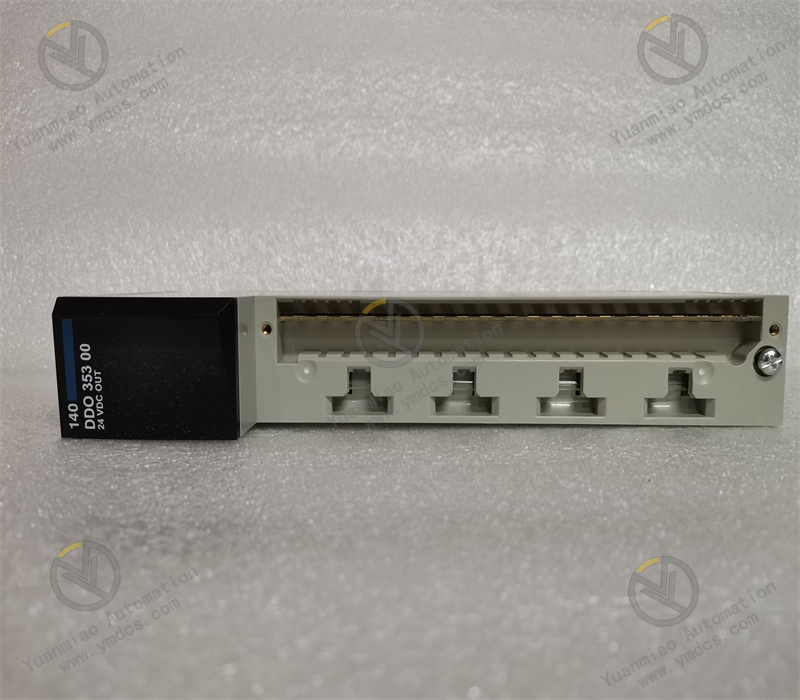
The YOKOGAWA F3SP21 - 0N is a module launched by Yokogawa Electric Corporation, which is applied in the field of industrial automation control. Series to Which It Belongs and Functional Positioning: It belongs to the Yokogawa FA - M3 series of PLC modules. This series is a new generation of programmable controllers. With its ultra-high-speed processing capability and stable control performance, it can achieve high-performance automation control. It integrates a compact design, saving space, supports flexible configuration, can cover up to 8,192 input/output points, and is equipped with various advanced modules, having a wide range of applications. Power Supply Specifications: It uses a 24VDC power supply, with an output of 5.0U/6.0A. It is suitable for 4 - 6 slot substrates and can stably supply power to the module itself and the connected devices. Input and Output Characteristics: It has the DC input sink/source function, with a voltage of 24VDC; the TR output is sink type, with a voltage of 24VDC and a current of 0.1A. There are 16 points for each, which can meet the signal input and output requirements of various field devices. Communication Function: It supports the link scanning communication mode. Through this mode, the data in the remote output (RY) of the master station can be sent to the remote input (RY) of all local stations, and the data in the remote register (RWw) of the master station can be sent to the remote registers (RWr) of all local stations, etc. This realizes the data interaction and sharing between the master station and the local stations, making it convenient to build complex distributed control systems. Application Fields: It is widely applied in many industrial fields such as numerical control machinery, metallurgy, oil and natural gas, petrochemical industry, chemical industry, paper making and printing, textile and dyeing, machinery, electronic manufacturing, automobile manufacturing, tobacco, plastic machinery, electric power, water conservancy, water treatment/environment protection, municipal engineering, boiler heating, energy, power transmission and distribution, etc., and can meet the automation control requirements in different industrial scenarios. Appearance and Installation: It usually has a compact appearance design and can be directly installed on a standard DIN rail, which is convenient for installation and layout in industrial control cabinets. While saving space, it ensures a firm installation and is convenient for maintenance and troubleshooting. Other Features: The module may have a certain anti-interference ability and can work stably in a complex industrial electromagnetic environment to ensure the accuracy and reliability of signal transmission. In addition, it may also have a diagnostic function, which can indicate the working status, fault information, etc. of the module through indicator lights or other means, making it convenient for operators to quickly locate and troubleshoot faults.
Installation and Debugging Steps of YOKOGAWA F3SP21 - 0N Module: Installation Steps: Preparation Work: Confirm that the module model matches the actual requirements, and prepare the tools needed for installation, such as a screwdriver. Ensure that the installation environment meets the requirements of the module, and avoid harsh environments such as high temperature, humidity, and strong electromagnetic interference. Turn off the power supply of relevant devices to ensure safety during the installation process and prevent electric shock and damage to the devices. Install the Module onto the Substrate: Since this module is suitable for a 4 - 6 slot substrate, carefully insert the module into the appropriate substrate slot. Ensure that the module is correctly aligned with the slot, and then use a screwdriver to tighten the fixing screws to firmly install the module on the substrate. Pay attention to avoiding physical damage to the module during the installation process. Power Connection: According to the power requirements of the module (24VDC), connect the power supply correctly. Connect the positive and negative poles of the power supply to the corresponding power terminals of the module respectively, ensuring a firm connection and avoiding unstable power supply caused by looseness. After the connection is completed, carefully check whether the power connection is correct to prevent errors such as reverse polarity connection. Input and Output Connection: For the input part (DC input sink/source, 24VDC, 16 points), connect the signal wires of external devices to the corresponding input terminals according to the actual control requirements. For example, if connecting a sensor signal, ensure that the connection of the signal wire is correct and has good contact. For the output part (TR output sink, 24VDC, 0.1A, 16 points), connect the devices that need to be controlled, such as relays, solenoid valves, etc. Also, ensure the correctness and firmness of the output connection. Communication Connection (if applicable): If the link scanning communication mode is used, connect the relevant communication cables according to the communication requirements, and correctly connect the master station and the local stations. Ensure that the connection of the communication cables complies with the regulations of the communication protocol, such as the requirements for cable shielding and grounding, to ensure the stability and reliability of communication. Debugging Steps: Check before Powering On: Before powering on the module, carefully check again whether all installations and connections are correct, including whether the module is firmly installed, whether the power connection is correct, whether the input and output connections are error-free, and whether the communication connection is normal, etc. Ensure that there are no looseness, short circuits, or other errors. Power-on Test: Turn on the power supply and observe the status of the indicator lights on the module. The module usually has a power indicator light, an operation indicator light, etc. Under normal circumstances, the power indicator light should be on, indicating that the module has been powered on. If an abnormal indicator light is on (such as a fault indicator light), it is necessary to troubleshoot the fault according to the meaning of the indicator light and the module manual. Input Test: Apply an appropriate signal (24VDC) to the input signal source and check whether the input indicator light of the module is normally on. Use the PLC programming software or other monitoring devices to check whether the input signal can be correctly read and processed. Each input point can be tested one by one to ensure the normal operation of the input function. Output Test: Send control signals to the output points of the module through the PLC programming software or other control means, and observe whether the connected external devices can operate as expected. For example, control the output points to make the relay pull in or the solenoid valve operate, and check the operation status of the devices. Similarly, each output point needs to be tested one by one to ensure the normal operation of the output function. Communication Test (if applicable): If the module supports the communication function, conduct a communication test. Use the corresponding communication tools or software to check whether the data transmission between the master station and the local stations is normal. Some test data can be sent and received to verify the accuracy and stability of communication. Check whether there are problems such as communication errors or data loss, and make debugging and settings as needed. Function Verification: Combine with the actual control requirements to verify the overall function of the module. For example, if the module is used to control a certain production process, simulate the actual production situation, check whether the mod

【 Disclaimer 】 We sell new products and discontinued products, independent channels to buy such special products. Guizhou Yuanmiao Automation Equipment Co., Ltd. is not an authorized distributor, dealer or representative of the products featured on this website. All product names/product images, trademarks, brands and microlabels used on this Website are the property of their respective owners. Descriptions, depictions or sales of products with such names/images, trademarks, brands and logos are for identification purposes only and do not imply any association or authorization with any rights holder. This article is from the official website of Guizhou Yuanmiao Automation Equipment Co., LTD. Please attach this link:http://www.ymdcs.com/Yokogawa/