Description
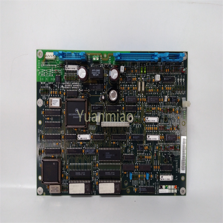
The YOKOGAWA AIP121 - S00 is an analog input module launched by Yokogawa Electric Corporation (YOKOGAWA), which plays an important role in industrial automation control systems. Functional Positioning: It is mainly used to convert analog signals from field devices (such as signals output by sensors for temperature, pressure, flow rate, liquid level, etc.) into digital signals, so that control systems (such as Distributed Control Systems, DCS) can process, display, record and control them. This module plays a key role in signal acquisition and conversion during the industrial production process, providing accurate data support for the automated control of the production process. Input Characteristics: Input Channels: It usually has multiple input channels (the specific number depends on the product specifications), which can simultaneously collect multiple analog signals, improving the collection efficiency and flexibility of the system. Input Signal Types: It supports various types of analog input signals, such as 4 - 20mA current signals, 0 - 10V voltage signals, etc., to adapt to different types of sensors and field devices. Accuracy: It has a high measurement accuracy and can accurately convert analog signals into digital quantities, ensuring the reliability of the collected data and meeting the requirements for measurement accuracy in the industrial production process. Communication Interface: Data transmission between it and the control system is carried out through a specific communication interface, such as fieldbus interfaces (such as Profibus, Modbus, etc.) or Ethernet interfaces, etc., to achieve efficient communication and data interaction with other devices. Adaptability to the Working Environment: The design takes into account the harsh environmental conditions of industrial sites. It has a certain anti-interference ability and can work stably within a certain range of temperature, humidity and vibration, ensuring reliability and stability in complex industrial environments. Installation and Maintenance: It adopts a standard industrial module design, making it easy to install on the standard rails of the control cabinet. The indicator lights and diagnostic functions of the module help to quickly identify the working status and fault information of the module, facilitating maintenance personnel to troubleshoot and perform maintenance operations, reducing maintenance costs and downtime. Application Fields: It is widely applied in the automation control systems of many industrial fields such as petroleum, chemical industry, electric power, metallurgy, pharmaceuticals, food and beverage, etc., to achieve precise monitoring and control of various analog parameters during the production process.
The installation and debugging steps of the YOKOGAWA AIP121 - S00 module are as follows:
Installation Steps
Preparation before Installation:
Environmental Inspection: Select an installation site that is dry and well-ventilated. The ambient temperature should be controlled within an appropriate range, such as 5°C to 35°C. At the same time, avoid environments with direct sunlight, strong electromagnetic field interference, and excessive dust.
Preparation of Tools and Materials: Prepare commonly used tools such as screwdrivers, wrenches, and multimeters, as well as materials such as screws, nuts, washers, cables, and plugs of various specifications. Also, prepare insulating materials such as insulating tape and insulating sleeves.
Module Installation:
Fixing the Module: Install the module in the control cabinet or on a suitable installation bracket. Use fixing devices such as screws to ensure that the module is firmly installed to avoid shaking or vibration during operation.
Connecting the Power Supply: Confirm the power supply requirements of the module, which is generally a 200V power supply. Connect the power cable that meets the requirements to the power input terminals of the module, ensuring a firm connection. Pay attention that the polarity of the power supply should not be reversed.
Connecting the Input and Output Signal Cables: According to the actual application requirements, connect the input signal cables of external devices to the input terminals of the module, and connect the signal cables of the devices that need to be controlled to the output terminals of the module. When connecting, ensure that the specifications of the cables meet the requirements, and the connections are firm and have good contact to avoid looseness or poor contact. At the same time, pay attention to the routing and layout of the cables to avoid crossing or tangling, and classify and label the cables for easy maintenance and troubleshooting.
Debugging Steps
Inspection before Debugging:
Hardware Inspection: Check whether the appearance of the module is damaged or deformed, and whether all components are firmly installed. Check whether the power connection is normal, and whether the power cable is damaged or short-circuited. Check whether various interfaces and plugs of the module are properly connected, and whether there is any looseness or poor contact.
Software Inspection: If the module requires relevant software configuration, check whether the software is successfully installed and can be started and run normally. Check whether the device driver is correctly installed and is compatible with the hardware of the module.
Power-on Test: Turn on the power supply of the module and observe the status of the indicator lights on the module. For example, the power indicator light should be on, indicating that the module has been powered on. If an abnormal indicator light is on (such as a fault indicator light), it is necessary to troubleshoot the fault according to the meaning of the indicator light and the module manual.
Input Signal Test: Apply an appropriate signal to the input signal source, and check whether the module can correctly read and process the input signal through the module's monitoring software or the control system connected to it. Each input channel can be tested one by one to ensure the normal operation of the input function.
Output Signal Test: Send control signals to the output channels of the module through the software or the control system, and observe whether the connected external devices can operate as expected. For example, control the output points to make the relay pull in or other actuators operate, and check the operation status of the devices. Similarly, each output channel needs to be tested one by one to ensure the normal operation of the output function.
Function Verification: Combine with the actual control requirements to verify the overall function of the module. Simulate the actual working scenario, check whether the module can correctly process the input signals and output the corresponding control signals to achieve the expected control function.
Parameter Adjustment: Adjust the parameters of the module according to the test results and actual application requirements. For example, set parameters such as the filtering time of the input signal and the response time of the output signal to optimize the performance and control effect of the module.

【 Disclaimer 】 We sell new products and discontinued products, independent channels to buy such special products. Guizhou Yuanmiao Automation Equipment Co., Ltd. is not an authorized distributor, dealer or representative of the products featured on this website. All product names/product images, trademarks, brands and microlabels used on this Website are the property of their respective owners. Descriptions, depictions or sales of products with such names/images, trademarks, brands and logos are for identification purposes only and do not imply any association or authorization with any rights holder. This article is from the official website of Guizhou Yuanmiao Automation Equipment Co., LTD. Please attach this link:http://www.ymdcs.com/Yokogawa/