Description
Some installation and maintenance precautions for the YOKOGAWA F3NC01 - 0N module: Installation Precautions: Environmental Conditions: Temperature: Ensure that the temperature of the installation environment is within the allowable operating temperature range of the module. Generally, the operating temperature of industrial modules is around 0°C - 55°C. Avoid installing it in high or low temperature environments, otherwise, it may affect the performance and service life of the module. Humidity: The relative humidity of the installation environment should be moderate, generally between 5% - 95% (without condensation). Excessive humidity may lead to short circuits or corrosion of electrical components, and too low humidity may cause electrostatic problems. Dust and Contaminants: Select a clean and low-dust installation site to avoid the module being affected by contaminants such as dust, oil stains, and corrosive gases. If the environment is relatively harsh, protective measures can be considered, such as installing a dust cover or installing it in a closed control cabinet. Electromagnetic Interference: Keep away from strong electromagnetic interference sources, such as large motors, transformers, frequency converters and other equipment. Electromagnetic interference may affect the normal operation of the module, resulting in communication errors or data loss. The module should maintain a certain safe distance from the interference source and ensure good grounding. Power Connection: Power Supply Specifications: Connect the power supply strictly according to the power requirements of the module. Confirm that the power supply voltage is 200V and ensure the stability and reliability of the power supply. Use appropriate power cables and pay attention to the correct connection of the power supply polarity to prevent the module from being damaged due to reverse connection. Power Protection: In order to prevent the module from being damaged by power fluctuations, overvoltage or overcurrent, power filters, voltage stabilizers or overcurrent protection devices can be considered for installation. Module Installation: Installation Location: Select an appropriate installation location to ensure that the module has enough space for heat dissipation and maintenance. A certain space should be reserved around the module to avoid being too close to other devices, which may affect the air circulation. Installation Method: Install it correctly in the control cabinet or other suitable installation brackets according to the installation instructions of the module. Use appropriate fixing devices to ensure that the module is firmly installed and avoid looseness or vibration during operation. Wiring Connection: When connecting the signal cables and power cables, ensure that the connections are firm and in good contact. Use appropriate wiring tools and wire according to the wiring diagram to avoid wiring errors. For communication cables, pay attention to shielding and grounding to improve the stability of communication. Communication Connection: Communication Interface: Confirm the type of communication interface and the communication protocol of the module, and select appropriate communication cables and connection methods. Configure and set according to the requirements of the communication protocol to ensure the normal communication between the module and other devices. Communication Distance: Pay attention to the length limit of the communication cable to avoid signal attenuation or communication errors caused by too long a communication distance. If it is necessary to extend the communication distance, repeaters or other communication expansion devices can be considered. Communication Settings: Before making the communication connection, ensure that the communication parameters of the module are set correctly, including baud rate, data bits, stop bits, parity check, etc. Improper settings may lead to communication failures or data transmission errors.
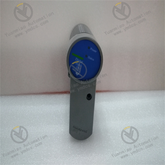
Maintenance Precautions: Daily Inspection: Appearance Inspection: Regularly check the appearance of the module to see if there are any abnormal conditions such as damage, deformation, or charring. If any abnormalities are found, stop using it immediately and carry out maintenance or replacement. Indicator Light Inspection: Observe the status of the indicator lights on the module to understand the working condition of the module. Under normal circumstances, the indicator lights should be displayed according to the specified status. If the indicator lights are abnormal, it may indicate that the module has a fault and further inspection and troubleshooting are required. Connection Inspection: Check whether the power connection, signal cable connection, and communication connection of the module are firm, and whether there are any looseness or poor contact. If there is any looseness, tighten it in time. Regular Maintenance: Cleaning Maintenance: Regularly clean the module to remove the dust and dirt on the surface. Use a clean soft cloth or a vacuum cleaner for cleaning. Avoid using wet cloths or corrosive cleaning agents to prevent damage to the module. Performance Testing: Regularly conduct performance testing on the module to check whether the functions of the module are normal. Professional testing equipment or software can be used for testing, such as testing the input and output signals and communication functions of the module. Software Update: Pay attention to the software update information of the module released by Yokogawa Electric Corporation and update the software of the module in a timely manner. Software updates can fix known problems and improve the performance and stability of the module. Troubleshooting: Fault Diagnosis: If the module malfunctions, first conduct a preliminary diagnosis according to the status of the indicator lights and the fault phenomena of the module to determine the possible causes of the fault. You can refer to the fault diagnosis manual of the module for troubleshooting. Fault Repair: Take corresponding repair measures according to the results of the fault diagnosis. If it is a hardware fault, it may be necessary to replace the damaged components; if it is a software fault, it may be necessary to reconfigure or update the software. Before carrying out the fault repair, ensure that necessary safety measures are taken to avoid accidents. Recording and Reporting: Record the fault situation and repair process of the module for future reference and analysis. If the fault of the module is serious or occurs frequently, report it to the technical support personnel of Yokogawa Electric Corporation in a timely manner to seek further help and solutions.

【 Disclaimer 】 We sell new products and discontinued products, independent channels to buy such special products. Guizhou Yuanmiao Automation Equipment Co., Ltd. is not an authorized distributor, dealer or representative of the products featured on this website. All product names/product images, trademarks, brands and microlabels used on this Website are the property of their respective owners. Descriptions, depictions or sales of products with such names/images, trademarks, brands and logos are for identification purposes only and do not imply any association or authorization with any rights holder. This article is from the official website of Guizhou Yuanmiao Automation Equipment Co., LTD. Please attach this link:http://www.ymdcs.com/Yokogawa/