Description
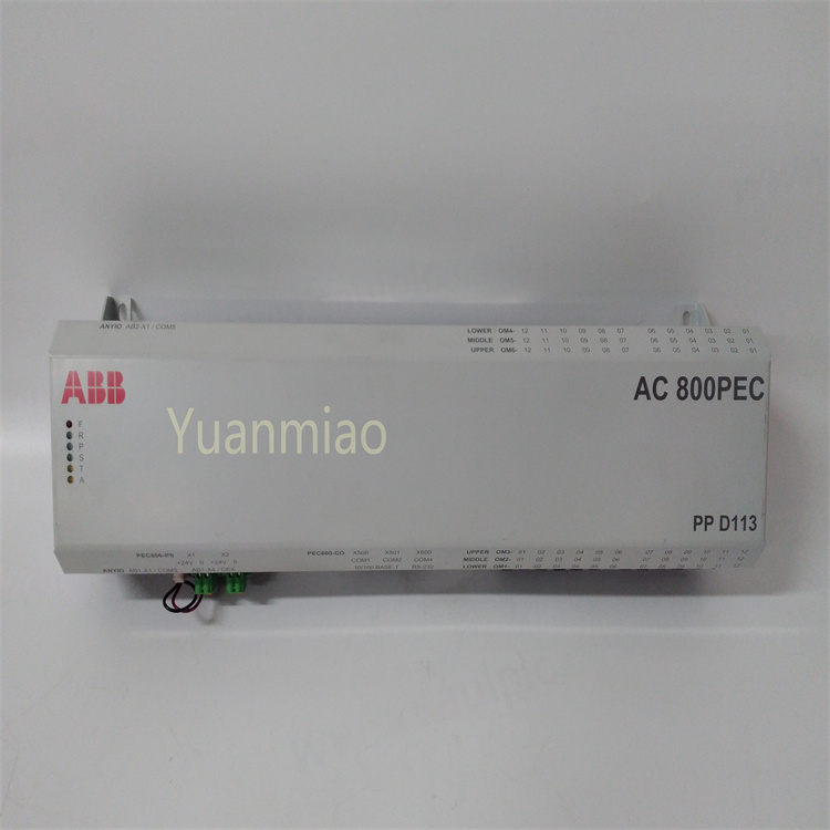
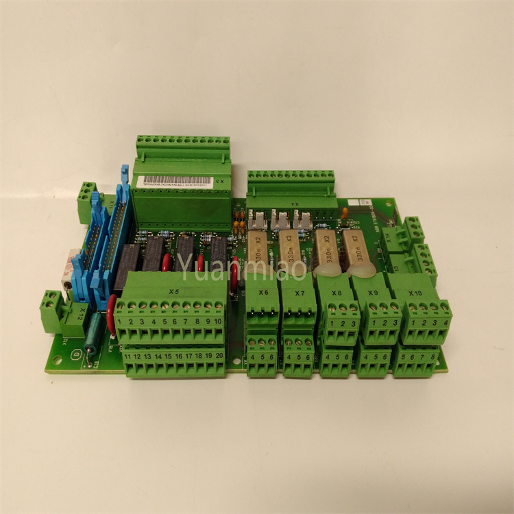
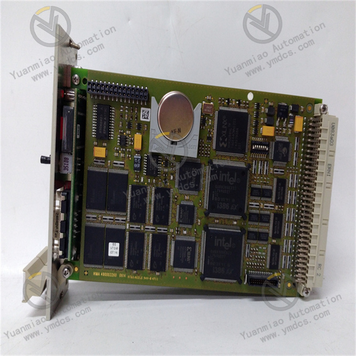
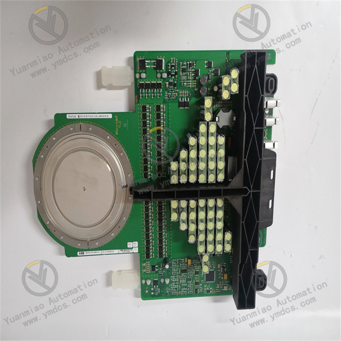
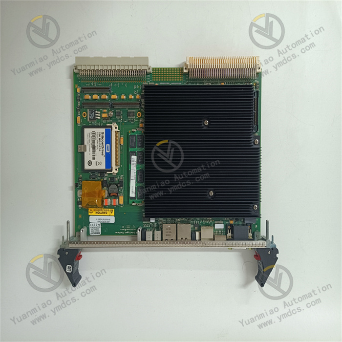
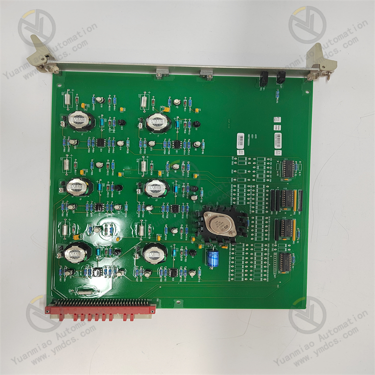
ALSTOM I/OBE2 12004 - 104 - 00 is an input/output bus expansion board of Alstom. In the field of industrial automation such as rail transit signaling systems, this type of board card from Alstom is usually used to achieve the functions of data transmission and signal expansion between devices. It may have a variety of interfaces and can be connected to other related devices such as controllers, sensors, and actuators, etc., in order to realize the information interaction and collaborative operation among different components in the system. Through this expansion board, the input and output signals can be flexibly allocated and expanded, meeting the requirements of complex control systems for signal processing and transmission, and helping to improve the reliability and flexibility of the entire system.
Installation Steps
1. Preparation Work: Confirm that the installation environment meets the requirements of the equipment, including conditions such as temperature, humidity, and dust prevention. At the same time, prepare the required tools, such as screwdrivers, wrenches, etc.
2. Inspect the Equipment: Before installation, carefully check whether the I/OBE2 module has any physical damage, and ensure that all interfaces, slots, etc. show no signs of deformation or damage.
3. Select the Installation Location: Choose a suitable installation location. It is usually recommended to install it inside the control cabinet to ensure there is enough space for heat dissipation and to facilitate subsequent maintenance operations. If it is installed on a DIN rail, make sure the rail is firmly installed.
4. Fix the Module: According to the installation method of the module, use the corresponding screws or clips to fix the I/OBE2 module in the selected position. If it is a plug-in module, ensure that it is inserted in place and locked.
5. Connect the Cables: Connect the corresponding input and output cables according to the interface definition of the equipment. Pay attention to the fact that the specifications and models of the cables should match the module, and the connection should be firm to avoid looseness or poor contact. At the same time, pay attention to grounding the shielding layer of the cables to reduce electromagnetic interference.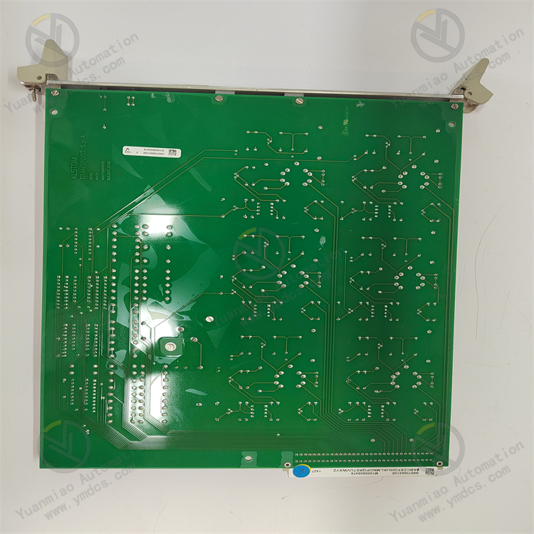
Configuration Steps 1. Confirm the Hardware Connection: Before performing the configuration, confirm again whether the hardware connection between the module and other devices is correct. 2. Install the Configuration Software: If the module requires specific configuration software, obtain it from the official Alstom website or the CD provided with the equipment and install it on the computer. 3. Connect to the Module: Connect the computer to the I/OBE2 module using an appropriate communication cable. It is usually possible to connect through a serial port, Ethernet port, or other dedicated communication interfaces. 4. Open the Configuration Software: Launch the configuration software and operate according to the prompts of the software, such as selecting parameters like the device type and communication port. 5. Set the Basic Parameters: In the configuration software, set the basic parameters of the module, such as the module address, communication baud rate, data bits, parity bit, stop bits, etc. These parameters need to be consistent with those of other connected devices to ensure normal communication. 6. Configure the Input and Output Functions: Configure the input and output functions of the module according to the actual application requirements. This may include setting the types of input channels (such as digital input, analog input, etc.), the types of output channels (such as digital output, analog output, etc.), as well as the corresponding functions and parameters of each channel. 7. Set the Alarm and Diagnosis Functions: Configure the alarm and diagnosis functions of the module as needed, so as to be able to issue an alarm in a timely manner and conduct fault diagnosis in case of abnormal situations. 8. Save the Configuration: After completing all the configurations, save the configuration information to the module. Some modules may also support saving the configuration as a file for subsequent backup and restoration. 9. Test and Verification: Before actual application, conduct testing and verification to ensure that the configuration of the module is correct and that it can work properly. You can check whether the input and output meet the expectations by sending test signals or simulating actual working conditions.

Main brands include: ABB, Bailey, GE, FOXBORO, Invensys TRICONEX, Bentley BENTLY, A-B Rockwell, EMERSON EMERSON, B&R, MOTOROLA, FUANC, REXROTH, KUKA, HONEYWELL, NI, DEIF, Yokogawa, WOODWARD WOODWARD, Ryan, SCHNEIDER SCHNEIDER, Yaskawa, MOOG, EPRO, PROSOFT and other major brands
【 Disclaimer 】 We sell new products and discontinued products, independent channels to buy such special products. Guizhou Yuanmiao Automation Equipment Co., Ltd. is not an authorized distributor, dealer or representative of the products featured on this website. All product names/product images, trademarks, brands and microlabels used on this Website are the property of their respective owners. Descriptions, depictions or sales of products with such names/images, trademarks, brands and logos are for identification purposes only and do not imply any association or authorization with any rights holder. This article is from the official website of Guizhou Yuanmiao Automation Equipment Co., LTD. Please attach this link:https://www.ymdcs.com/ALSTOM/