Description
Features and Functions:
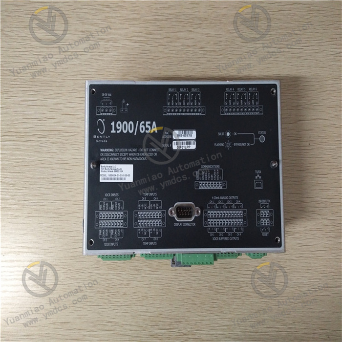
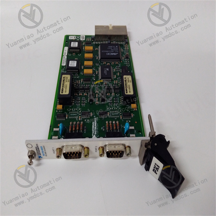
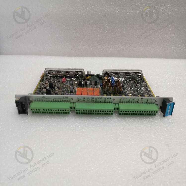
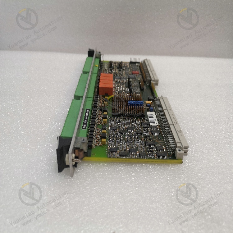
Signal Interface: It serves as the signal interface for the MPC4 mechanical protection cards in the Vibro - Meter® VM600 series. It has 4 dynamic signal inputs and 2 tachometer inputs, and supports screw - terminal connections.
Relays and Outputs: It includes 4 relays that can be used for alarm signals under software control. It also has 32 fully programmable open - collector outputs, which are connected to the IRC4 and RLC16 relay cards.
Signal Processing and Protection: It provides EMI protection for all inputs and outputs and has a hot - swap function. It can connect the original dynamic (vibration) and speed signals from sensors to the MPC4, and after processing, the signals are sent back and provided on the front - panel terminal block. For dynamic signals, four on - board digital - to - analog converters can provide calibrated signal outputs in the range of 0 to 10V, and four on - board voltage - to - current converters can also provide current output signals in the range of 4 to 20mA (jumper - selectable).
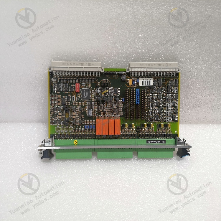
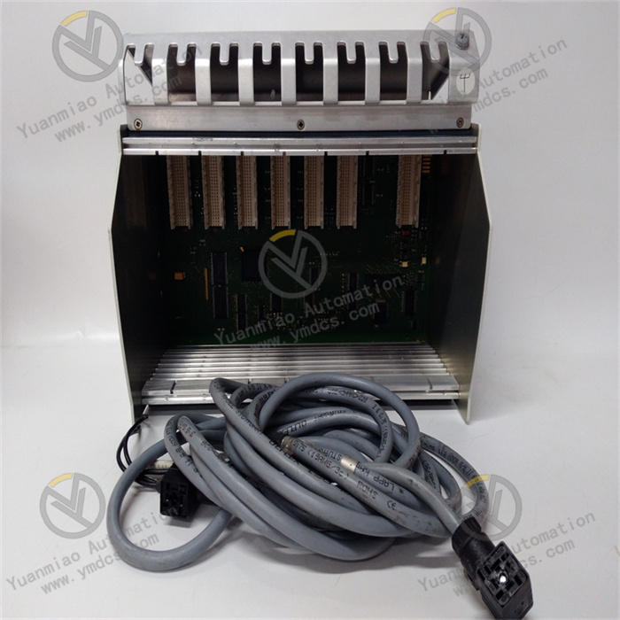
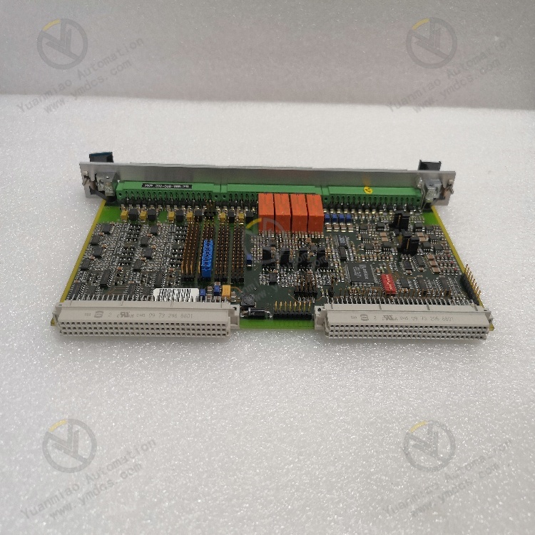
Installation Method: It is installed at the rear of the VM600 rack and is directly connected to the rack backplane through two connectors. It is associated with the corresponding MPC4 card and is directly installed behind the VM600 rack (ABE04x or ABE056). It operates in a slave mode and communicates with the MPC4 through the industrial package (IP) interface using connector P2.
Alarm Reset Function: A closed contact between the DSI AR and DSI RET inputs can reset (clear) the locked alarms of the MPC4/IOC4T card pair.
In addition, the front panel of the IOC4T card is equipped with BNC connectors for easy analysis of the buffered "raw" sensor signals, and there are also LEDs to display the status and alarms. It is designed to be used with the second - generation VM600 Mk2 rack - based mechanical protection system and is widely applied in modern industrial fields such as power, petroleum, and mines, suitable for mechanical protection and condition monitoring.
The Vibro - meter VM600 IOC4T is an important input/output module in the VM600 system. Correct installation and commissioning are crucial for ensuring the normal operation and accurate monitoring of the system. The following are the general steps and key points for the installation and commissioning of the Vibro - meter VM600 IOC4T:
Before starting the installation, ensure that all necessary tools and accessories, such as screwdrivers and wrenches, are ready. Confirm that the installation environment meets the requirements of the device, including power supply, temperature, and humidity conditions. At the same time, carefully read the installation manual of the VM600 IOC4T to understand its installation requirements and precautions.
The IOC4T is usually installed in the rack of the VM600 system. First, determine a suitable installation position on the rack. Generally, it needs to be installed behind the MPC4 card or the MPC 4 SIL card to form a card pair. Use tools like screwdrivers to fix the IOC4T module on the rack, ensuring a firm installation to avoid loosening during operation.
- Power Connection: Connect a suitable power supply according to the power requirements of the IOC4T. Usually, its operating voltage is 220V, but please refer to the device manual for specific details. Ensure the power connection is correct to avoid short - circuits or other electrical faults.
- Signal Connection: Connect the signal wires of the sensors to the corresponding input ports of the IOC4T. The IOC4T supports 4 dynamic channels and 2 speed (tachometer) channels, and all channels can be configured independently. Connect the signal wires correctly according to the type and signal characteristics of the sensors, and ensure a firm connection to avoid signal interference or loss.
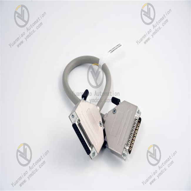
- Communication Connection: If communication with other devices, such as PLCs or host computers, is required, connect the corresponding communication cables. The IOC4T may support communication protocols such as RS - 485 and Modbus, and the connection should be made according to actual needs.
- Relay and Output Connection: The IOC4T is equipped with four configurable relays, each with two contacts. Connect the outputs of the relays to the corresponding devices, such as alarm devices or control devices, according to actual application requirements. At the same time, connect the 32 fully programmable open - collector outputs to the IRC4 and RLC16 relay cards, ensuring correct connections.
Before turning on the power, check again whether all electrical connections are correct. After turning on the power, observe whether the power indicator on the IOC4T module lights up. If the indicator does not light up, check the power connection and whether there is a fault in the module.
The IOC4T module usually has a self - test function. After turning on the power, the module will automatically perform a self - test. Observe the status indicators on the module to understand the self - test results. If an error occurs during the self - test, find and solve the problem according to the prompts of the indicators or the fault codes in the device manual.
Use a suitable signal source to input analog signals to the input channels of the IOC4T to check whether the module can correctly receive and process the signals. You can check whether the measured values of the input signals are accurate by observing the signal indicators on the module or using relevant test software. If the measured signal values are inaccurate, check the signal connection, the sensor, or the configuration of the module.
If the IOC4T communicates with other devices, conduct a communication test. Use communication test tools or relevant software to check whether the module can communicate normally with other devices. Ensure that the communication parameters, such as baud rate and data format, are set correctly. If the communication fails, check the communication cables, interfaces, and parameter settings.
Perform corresponding function tests according to the specific functions of the IOC4T. For example, test whether the relays operate normally and whether the output signals meet the expectations. For configurable functions, such as alarm set points and signal filtering, make corresponding settings and tests to ensure the normal operation of the functions.
After completing the individual commissioning of the IOC4T module, conduct joint commissioning with the entire VM600 system. Check whether the system can operate normally and whether the cooperation between various modules is normal. Verify whether the performance and functions of the system meet the requirements through actual operation tests.

Main brands include: ABB, Bailey, GE, FOXBORO, Invensys TRICONEX, Bentley BENTLY, A-B Rockwell, EMERSON EMERSON, B&R, MOTOROLA, FUANC, REXROTH, KUKA, HONEYWELL, NI, DEIF, Yokogawa, WOODWARD WOODWARD, Ryan, SCHNEIDER SCHNEIDER, Yaskawa, MOOG, EPRO, PROSOFT and other major brands
【 Disclaimer 】
We sell new products and discontinued products, independent channels to buy such special products. Guizhou Yuanmiao Automation Equipment Co., Ltd. is not an authorized distributor, dealer or representative of the products featured on this website. All product names/product images, trademarks, brands and microlabels used on this Website are the property of their respective owners. Descriptions, depictions or sales of products with such names/images, trademarks, brands and logos are for identification purposes only and do not imply any association or authorization with any rights holder.
This article is from the official website of Guizhou Yuanmiao Automation Equipment Co., LTD. Please attach this link:https://www.ymdcs.com/Vibro-meter/
![]()